[BUILD] 1176LN Rev D DIY

GroupDIY Audio Forum

Help Support GroupDIY Audio Forum:

This site may earn a commission from merchant affiliate links, including eBay, Amazon, and others.
Hi

If your DMM has a HFE socket, simply turn the weel (or the menu) and install them in this socket
Trisonic-transistor-gain-hFE-test-socket.jpg


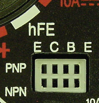
BAsically, the 3708 are NPN (Not-Pointing-In :p and the letters mean each of the legs/connectors. (check datasheet, simply google for 2n3708 and whatever manufacturer you got for and look at the pinout (eg. CBE when looking at the transistor on the flat side).

Try and match them. And make sure you get hfe>250 for the required ones (See BoM).

Alternatively, you can get an Atlas Peak http://www.peakelec.co.uk/acatalog/jz_dca55.html worth it if you think of making more clones and neve-esk stuff etc
 
Hello All,

This more of a comment than a question, a search gave me nothing on this so I thought I would post it for others building the 1176.

I was having consistent problems with a couple of MNATS power supplies I'm working on, in that R2 (The LED Resistor on the positive 30V rail) would burn out after a few minutes. In the end I calculated that with a 20ma/2.3V LED, the resistor would need to dissipate over 0.5Watt, hence the smoke after a few minutes.

I ended up jamming a 5watt wirewound resistor in there and it works great.

This is the PSU in question, which I am using in a stereo Rev J build:
http://mnats.net/psu.html
 
I'll try and keep this short.

Basically, I have a Stereo 1176 Rev D build, everything seems to be functioning okay.
I am calibrating the unit with a function generator outputting a sine wave @ 1kHz 0dBm @ 0.775Vrms.

After I calibrate my unit there is no compression, but if i mess around with the Q-bias a little it starts compressing at various points of resistance on the trimmer.

What does this mean? My function generator is from a BNC output @ 50ohm into pins 2&3 of the XLR (positive and negative) respectively.

If it helps I can measure voltages...

Thanks!
 
braeden said:
I'll try and keep this short.

Basically, I have a Stereo 1176 Rev D build, everything seems to be functioning okay.
I am calibrating the unit with a function generator outputting a sine wave @ 1kHz 0dBm @ 0.775Vrms.

After I calibrate my unit there is no compression, but if i mess around with the Q-bias a little it starts compressing at various points of resistance on the trimmer.

What does this mean? My function generator is from a BNC output @ 50ohm into pins 2&3 of the XLR (positive and negative) respectively.

If it helps I can measure voltages...

Thanks!

Try this:

Use a good DMM (that can handle 1K AC) rather than the meter.

Send a 1K tone and check the level at the input (across pin 2 and 3).  You may find you'll have to send closer to +2dbu or something from your generator to get 0dbu at the input due to impedance loss.  Once you know you're getting 0dbu at the input (0.775VAC across 2 and 3), move the DMM to the output and run your qbias and tracking adjustments.  You'll know 100% it's working correctly if you do it right.

Mike
 
jplebre said:
Try and match them. And make sure you get hfe>250 for the required ones (See BoM).

I just bought a $10 DMM with a HFE/transistor plug.  They all measure between 440 and 465.  Is it best to use the tightest grouping or the highest values?
 
tightest grouping for Q12/Q13 (so that meter tracks better). Then AFAIK after hfe>250 it's diminishing returns really.

HFE in most cases has to do with clearing noise floor, but this is not the case here (this section is generating a control voltage with the help of the diodes). I would think (again, this is me guessing) that the requirement is there to meet biasing requirements. There are lots of feedback networks and I seem to remember that in more than one project someone commented that in those designs, hfe did not mater as much

 
Wonderful - thanks for your advice and explanation Jplebre  8)  I like to know exactly how i'm changing outcomes with each change and it certainly helps my learning curve.

I have a few 3708's with mirror HFE readings so i'll pull out my Q12 & 13 of unknown value and use these for the meter.
 
mnats said:
I noticed that the trimmer potentiometers in this image appear to be mounted incorrectly (so that all three pins are shorted together).

So it appears this was the problem! Changed the trimmers, fired up the 1176, calibrated the unit and tested it on some vocals. All great!

One stupid mistake though.. I reversed the output pot! Fully CW is no signal while fully CCW gives the most output ::)
Is this resolved by switching the red, positive wire with the ground wire on the back of the OP pot?
 
thesystem said:
Is this resolved by switching the red, positive wire with the ground wire on the back of the OP pot?

Yes
Or if you installed molex terminals on the PCB, just swap them on the PCB side
 
Perhaps this is obvious to others, but it's lost on me - is there a reason why the zero trim pot is accessible via the front panel rather than being solely dealt with on the circuit board?
 
jplebre said:
thesystem said:
Is this resolved by switching the red, positive wire with the ground wire on the back of the OP pot?

Yes
Or if you installed molex terminals on the PCB, just swap them on the PCB side

Cool, did that, started recalibrating. But now I get stuck at the 3rd step of the calibration! I apply a 1 kHz tone @ 0 dBm as stated at 2:18 in the video and adjust the output pot to read 0 VU on the meter. So far so good. Then when I switch the attack pot from 'off' to 'on' nothing happens! While when I was doing the calibration when I had the OP pot reversed the whole calibration process went smoothly. What am I doing wrong? Is it because I switched the ground and positive wire on the molex terminals on the PCB it's not working any more?

EDIT: Also, tried to compress some audio and it seems that the meter is compressing in the wrong direction.. while the +4 seems to work fine.
 
Yes. Sorry I probably gave you a bit of a wrong advice.
Swapping the wires would mean that now your compression is tapping of from the ground, not from the signal (pre O/p pot).

Sorry about that!
example.jpg
 
jplebre said:
because you'll find yourself constantly reaching for it :p

Is this a source dependent factor or does the gauge naturally wander from zero over time?  I ask this as i'm not really one to pay attention to meters, and seeing I just bought a Hairball Rev A I may just keep the zero trimmer on the PCB.
 
drifts with temperature. When I bring my 1176's home they drift if the kettle is on, or the dishwasher, by as much as +-2 :S

Edit: and when I move studios I notice it's never spot on (even when I callibrated it last after being on for a while and warm etc.)
 
jplebre said:
Yes. Sorry I probably gave you a bit of a wrong advice.
Swapping the wires would mean that now your compression is tapping of from the ground, not from the signal (pre O/p pot).

Sorry about that!
example.jpg

No problem :) already glad you guys are helping! There's still one thing that isn't suppose to happen. When the unit is compressing some audio (in GR mode) the meter also moves upwards into the red area on the VU meter. But only when it's compressing. It is as if the meter is trying to show the compression while also trying to show the level going out (as if in +4 mode). When I leave the OP pot down and turn up the input, the meter shows the proper compression values. As soon as I turn up the OP pot the meter starts combining the compression and +4 movement.
I don't understand why it is doing this. Is it because something is shorting?
 
I take it you can't complete callibration procedures either?
Check for the usual suspects first. Although, if you are saying that the meter tracks fine on O/p, you should be able to narrow down the fault to the GR section or to the cables between the far left side of the board to the meter board.

Check your cabling again, check how you left the jumper after callibration procedures and try and compare voltages against mnats schemo. You may be able to find the culprit.
http://mnats.net/files/1176REVD_VOLTS.pdf
 
Here are the voltages:

rails:

-9,69
+29,73

            b      c      e
Q2: 1,06 - 1,78 - 0,55
Q3: ---    - 11,77 - 1,16 --> c:12,58
Q4: 1,01 - 4,25 - 0,43
Q5: 3,18 - 24,76 - 2,61 --> c:26,18
Q6: ---    - 27,22 - 2,2 --> c:28,93
Q7: 4,49 - 14,8 - 3,94 --> c:15,25
Q8: ---    -  ----    - 14,17 --> e:14,7
Q9: 3,44 - 16,86 - 2,88
Q10: ---  -  ---    - 16,28
Q11: ---  -  ---    - 9,67 --> e:10,56
Q12: -0,77 - 8,34 - -1,37 --> c:9,28
Q13: -0,91 - 8,92 - -1,48 --> c:9,75
Q14: ---    -  ----  - 11,16 --> e:12

All the numbers seem fine. I marked some of them bold because I don't know how much the numbers are allowed to deviate from the numbers on the voltage schemo and these numbers differ the most. If someone could tell me? I put the voltages from the schemo behind my results.
 
Can I get an ID on the fuse rating I need to run @240V?  Mnat's build guide suggests i'm looking for a 63mA fuse, but I have a feeling I should be after a 125mA?
 

Latest posts

Back
Top