[BUILD] 1176LN Rev D DIY

GroupDIY Audio Forum

Help Support GroupDIY Audio Forum:

This site may earn a commission from merchant affiliate links, including eBay, Amazon, and others.
If you want to do a basic functionality test on your transformer:

1. Disconnect it from everything.
2. Get your DMM and set it to Ω
3.  Measure the resistance of each primary winding.  Should be about 39.75Ω.
4. Measure the resistance of each secondary winding.  Should be about 3.75Ω.
5. Measure one lead from each winding against each of the other windings.  Should be infinity.

Mike
 
OK I will test my transfo now. 

I still don't understand why one works perfectly and one doesn't when the one that works has the power wired with the two 0v secondaries wired to the CT.  We changed the wiring on that one to how you have instructed and now it doesn't work. 

We had it fully calibrated and compressing audio.  sounded great but it was not wired the way you are telling us to do it.  Now we have rewired it to match your directions and the unit wont even power on anymore. 

So why are the laws of physics and reality fighting each other? 

My testing methods have all been as you describe them and my components are all placed as they should be.  I have checked that 100 times over.
 
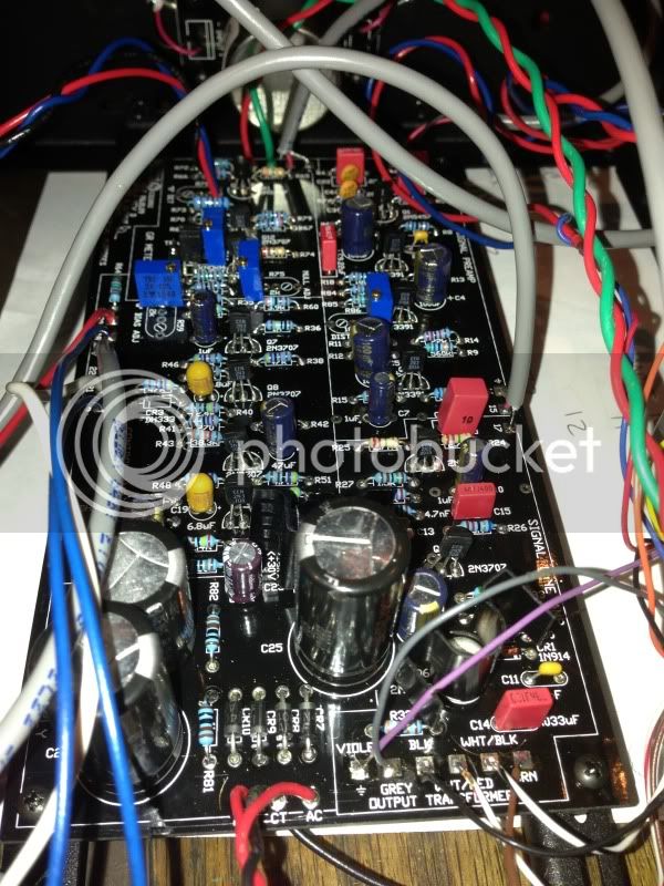
Are you sure your power supply is stuffed correctly? That may be your issue and why things seem off.  Maybe post an image of you power supply section.
 
Hi guys,

I've just finished building 3 Rev D 1176's and 1 Rev A.

They all sound great, however all of the Rev D's have a noisy output pot which you can only hear when you turn the pots. They're all Alpha 250k pots and I've thoroughly flushed them out with deoxit D5 and no luck. I don't have the same problem on the Rev A and all my wiring is the same.

Any ideas what's causing this noise? I've attached an MP3 of the noise.

Thanks!
 
Hi all,
This is my first post here, as well as my first diy build. After searching for hours, I've found nothing on the problem at hand.

When I first powered on the unit, the vu lamp went on, nothing smoked or popped, so I was thrilled.  I hit the "off" button on the meter switch and everything shut off. Unfortunately, now no matter what I press nothing happens.  I checked the fuse.. it's fine.

Any help would be appreciated.  Be gentile with me.
 
Peart, if you wired the power using one of those terminal connectors, make sure (with it NOT plugged in) that nothing came loose there and check continuity from that terminal block to wherever its going.  Also, is it possible its working and the lamp just blew?  If you didn't have the right resistor on it you might have killed the light.  After you check that, take some readings on at the PS and see if you're atleast getting power into the unit from the switch.  & BE CAREFUL!
 
okay im back, soldering iron died and i just got a hold of another...

any way back to my issue.. i have been doing a ton of research and i think i have found my issue in the GR Meter Driver Circuit....

my Q11 is reading about 15.44V on the drain instead of the typical 10.56V

my Q12  has  B -2.20V C 15.38V E -2.08 typical voltages are -.9V, 9.28V, -1.52V 

Q13 ha a B -1.20V C 14.28V E -1.79  typical voltges -1.04V , 9.75V, -1.63V

                     
my meter does not go past 2 MOhm so im guessing but i think it must be R74 that is the issue ( tested R79 and R67 and they are fine).

my first guess was it was R65 controlling the gate of Q11


do yall think that could be my issue?

 
I finished wiring up my build (had the minor issue with the PSU, the rest of the build went quite smoothly), but something just isn't quite right. I tested every single resistor for the correct value upon installation, and followed the wiring guide to the best of my abilities. Tomorrow I will reflow all solder joints, check for shorted wires/mis-wires, and compare voltages to the schematic. But, as usual I have the issue on my mind and wanted to see if my situation points to anything in particular:

Basically I plugged it in and rigged it up to calibrate. Meter is perfect brightness, nothing is smoking, fuse is intact. However, my meter didn't want to calibrate for Q bias. Actually, it didn't want to move. The only way I could make it move was by turning the output knob to around 80% and then it would pin far right. I double checked my calibration knob/button settings.

Yesterday I didn't really have the proper cabling to connect to the patch bay, so I will say I don't know if it passes audio or not. I can't rule out bad cabling as the culprit there. I just figured I would calibrate before even trying audio.

Any ideas come to mind for me to check first?
 
tronnyjenkins said:
I finished wiring up my build (had the minor issue with the PSU, the rest of the build went quite smoothly), but something just isn't quite right. I tested every single resistor for the correct value upon installation, and followed the wiring guide to the best of my abilities. Tomorrow I will reflow all solder joints, check for shorted wires/mis-wires, and compare voltages to the schematic. But, as usual I have the issue on my mind and wanted to see if my situation points to anything in particular:

Basically I plugged it in and rigged it up to calibrate. Meter is perfect brightness, nothing is smoking, fuse is intact. However, my meter didn't want to calibrate for Q bias. Actually, it didn't want to move. The only way I could make it move was by turning the output knob to around 80% and then it would pin far right. I double checked my calibration knob/button settings.

Yesterday I didn't really have the proper cabling to connect to the patch bay, so I will say I don't know if it passes audio or not. I can't rule out bad cabling as the culprit there. I just figured I would calibrate before even trying audio.

Any ideas come to mind for me to check first?

Are you sure you're starting with the bias in the right position? Set it so the DC at the gate of Q1 is as negative as it will go then try the calibration step again.

Mike
 
Echo North said:
Adam,

Please refresh me.  Are you just having a meter issue?  Is your build passing audio?  Compressing?

Mike

right now i have some how gone backwards... i am getting no audio to pass through now...
all I am now getting is a bunch of fuzz. not distorted audio just fuzz. the fuzz seems to only be affected by the output knob, when fully clockwise the fuzz cuts out. no matter the position of input and out put the fuzz does not change level until it cuts out at fully CW on the Output.

I did change a few components before this. i replaced Q12 and Q13, R74 as wella s R4 because it tested low going through the board.

before tested this time I completed Discrete meter calibration last night and had gotten the Drain from Q11 don to about 13V 
 
is it normal to see sparks in a POT? im guessing no and that my output pot is broken.... it would explain my fuzz problem and the issue of it cutting out at the fully CW position.


and I am passing an audio signal now in both VU and GR modes
 
berkleystudios said:
is it normal to see sparks in a POT? im guessing no and that my output pot is broken.... it would explain my fuzz problem and the issue of it cutting out at the fully CW position.


and I am passing an audio signal now in both VU and GR modes

Nooooooooooo.

Are you sure you have that wired correctly?!?!

I would do over ALL of the wiring against the MNATS wiring step by step guide.

I can send you a new pot, but you should make sure it's not a wiring error that is damaging the pot first.

Mike
 
I have rewired it several times against Mnats wiring guide, I even rechecked it today after noting the small sparks or arcing going on inside of the pot. but I will check it again

 
berkleystudios said:
I have rewired it several times against Mnats wiring guide, I even rechecked it today after noting the small sparks or arcing going on inside of the pot. but I will check it again

That sounds like a pretty serious issue.  Do you have significant DC in your pot?  Check the lugs against ground.
 
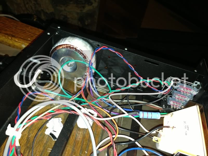
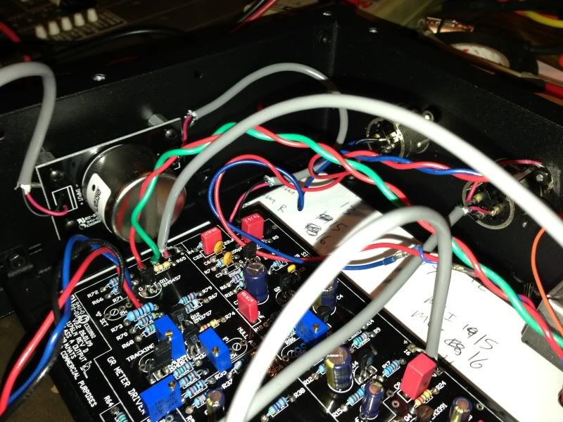
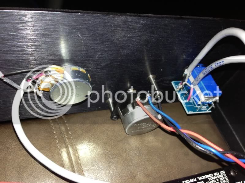
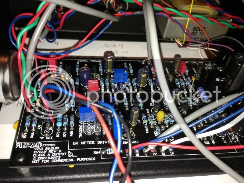
I'm not sure what the issue is, but I'm not passing audio either. The q bias turned completely off cured the meter slam however. What should I check?

null_zps387132f1.jpg


null_zps0af013cb.jpg


null_zps02ed8aa5.jpg


null_zps7b84c4ab.jpg


null_zps73e82730.jpg
 
Echo North said:
berkleystudios said:
I have rewired it several times against Mnats wiring guide, I even rechecked it today after noting the small sparks or arcing going on inside of the pot. but I will check it again

That sounds like a pretty serious issue.  Do you have significant DC in your pot?  Check the lugs against ground.


odd at home with no signal going through it there is no dc and no arcing in the pot. there is resistance in the pot.... is it possible that when signal is applied that it can create dc in the pot? (cant test with a signal at home)
 
Have you checked your DC voltages against the MNATS schematic on his site?

Start there.  Then we can trace the signal, see where it dies.
 
Back
Top