[BUILD] 1176LN Rev D DIY

GroupDIY Audio Forum

Help Support GroupDIY Audio Forum:

This site may earn a commission from merchant affiliate links, including eBay, Amazon, and others.
mnats said:
FairFax said:
Thanks for replying.

Aha! I see there is an issue here, with no recordable voltage at the 8:1 and 4:1 ratios (see below).

With a 1kHz tone input at .775VAC, AC value's at PCB pad 22  are ..
20:1 = .448
12:1 = .217
8:1  = .0
4:1  = .0

Any thoughts?

Probably one of the three dot points listed in the FAQ linked from the first post of this thread.

I'm in the process  of checking all component values, solders and wiring. My builds are always very methodical (triple check everything) but clearly I've made a silly mistake somewhere.

One last question .. what should the voltages be at Pad 22 (C17)?

Currently with a 1kHz tone input at .775VAC, and input control at 12 o'clock, my AC value's at PCB pad 22  are ..
20:1 = .448
12:1 = .217
8:1  = .0
4:1  = .0

Thanks
 
FairFax said:
mnats said:
FairFax said:
Thanks for replying.

Aha! I see there is an issue here, with no recordable voltage at the 8:1 and 4:1 ratios (see below).

With a 1kHz tone input at .775VAC, AC value's at PCB pad 22  are ..
20:1 = .448
12:1 = .217
8:1  = .0
4:1  = .0

Any thoughts?

Probably one of the three dot points listed in the FAQ linked from the first post of this thread.

I'm in the process  of checking all component values, solders and wiring. My builds are always very methodical (triple check everything) but clearly I've made a silly mistake somewhere.

One last question .. what should the voltages be at Pad 22 (C17)?

Currently with a 1kHz tone input at .775VAC, and input control at 12 o'clock, my AC value's at PCB pad 22  are ..
20:1 = .448
12:1 = .217
8:1  = .0
4:1  = .0

Thanks

Have a look at the schematic.  Mainly the resistor ladder R19 ->R22.  The 4 and 8 ratios are at the end of the ladder.  Your signal is ending there, you should see the AC get smaller as you go down but not drop to zero.  You have a bad pad, trace around R20.

Do some continuity testing.

Mike
 
Hairball Audio said:
Have a look at the schematic.  Mainly the resistor ladder R19 ->R22.  The 4 and 8 ratios are at the end of the ladder.  Your signal is ending there, you should see the AC get smaller as you go down but not drop to zero.  You have a bad pad, trace around R20.

Do some continuity testing.

Mike

Thanks Mike. I've been reading the schematic and it never occurred to me to check continuity across the resistor ladders. So obvious! I've been checking components (which I checked before stuffing) and it occurred to me it might be a dodgy switch, but unlikely I think.

When I've found and fixed the fault I'll post again.

Cheers
 
Brand new to DIY. Completed the build, and started to calibrate q-bias. 1k Tone at .775 goin into xlr input verified. But, when I turn the input knob up, the signal starts to "pulse" , and the meter moves up and down. That's without touching it! Also, when I monitor output from xlr back into PTools, it doesn't sound like the 1k tone :). I've checked all wiring. I've checked polarization/orientation of capacitors/diodes/etc. I tested every single resistor before stuffing. Not sure what to do at this point. Very frustrated, and about to throw 600 bucks and this thing in the garbage. It's been sitting in the corner waiting to be finished for weeks, and everytime I sit down to try and figure it out I get stuck in a loop of not knowing where to look, or where to start. Thanks in advance.
 
FairFax said:
Hairball Audio said:
Have a look at the schematic.  Mainly the resistor ladder R19 ->R22.  The 4 and 8 ratios are at the end of the ladder.  Your signal is ending there, you should see the AC get smaller as you go down but not drop to zero.  You have a bad pad, trace around R20.

Do some continuity testing.

Mike

Thanks Mike. I've been reading the schematic and it never occurred to me to check continuity across the resistor ladders. So obvious! I've been checking components (which I checked before stuffing) and it occurred to me it might be a dodgy switch, but unlikely I think.

When I've found and fixed the fault I'll post again.

Cheers

Problem fixed and all ratio buttons working as expected. Although I could see no visibly dodgy pads or solders and couldn't find any in-circuit continuity issues on my ratio board, I decided to remove and re-solder the resistors.

This solved the issue. Lesson learnt. No matter how perfect a solder may look, there may still be an issue.

Thanks Mike and Mnats for helping.
 
lukeadams said:
Brand new to DIY. Completed the build, and started to calibrate q-bias. 1k Tone at .775 goin into xlr input verified. But, when I turn the input knob up, the signal starts to "pulse" , and the meter moves up and down. That's without touching it! Also, when I monitor output from xlr back into PTools, it doesn't sound like the 1k tone :). I've checked all wiring. I've checked polarization/orientation of capacitors/diodes/etc. I tested every single resistor before stuffing. Not sure what to do at this point. Very frustrated, and about to throw 600 bucks and this thing in the garbage. It's been sitting in the corner waiting to be finished for weeks, and everytime I sit down to try and figure it out I get stuck in a loop of not knowing where to look, or where to start. Thanks in advance.

Read here:
http://groupdiy.com/index.php?topic=29981.msg754314#msg754314

Check DC at pad 18 and 7 and described in those posts.

Mike
 
Cool. Thanks Mike for your responses and your patience with a newbie. Having said that- when I said
"total newbie" - what that means is this: when you say check DC at Pad 18 and 7...I have no idea what you are talking about. :) Yes, I have a DMM. I know how to turn it to DC. I have a red and black probe all ready to go. I have a PDF of the schematic. The only "18" I see on it is where the brown wire goes into the PCB from attack pot. I see empty holes on the edges of the PCB- but they aren't numbered. They aren't shown in the schematic. Any help is appreciated. Thanks.
 
lukeadams said:
Cool. Thanks Mike for your responses and your patience with a newbie. Having said that- when I said
"total newbie" - what that means is this: when you say check DC at Pad 18 and 7...I have no idea what you are talking about. :) Yes, I have a DMM. I know how to turn it to DC. I have a red and black probe all ready to go. I have a PDF of the schematic. The only "18" I see on it is where the brown wire goes into the PCB from attack pot. I see empty holes on the edges of the PCB- but they aren't numbered. They aren't shown in the schematic. Any help is appreciated. Thanks.

Did you check your power supply voltages as instructed in the build guide?  Same concept.  Black probe on a common point (like power supply CT) and red on pad 18 on the main PCB.  Then Pad 7 on the main PCB.  If your terminal blocks are covering the pad numbers, refer to the MNATS board overlay.

http://mnats.net/files/1176LN_REVD_V2.2_DOC.pdf

Mike
 
thanks mike-

yes. tested the power supply/case continutity BEFORE starting anything else as per the build guide. Did it w a friend who has built two Hairball Rev A's. He said all looked good. Unfortunately, he's out of pocket and I can't consult him.

Okay. Found the "CT" on the power supply area by looking at the schematic (mnats Rev D). When I measure DC with the DMM, touching red probe at flat head screw at top of pad 18 and the black probe on the top of flat head screw on power supply CT (i'm using the header blocks) I get a reading of -2.351 VDC. Pad 7 yields a reading of  0.000 VDC. Zilch. :) ?

Also- holding both probes in place (red on Pad 18, and black on PSupply CT) and turning q-bias yields: turning CW makes the reading go from -2.35 to -2.15 , and the CCW makes the reading go from -2.351 to -2.50.

Same procedure with Pad 7 yields no change in DMM reading. 0.00 no matter what I turn on r59.
 
lukeadams said:
thanks mike-

yes. tested the power supply/case continutity BEFORE starting anything else as per the build guide. Did it w a friend who has built two Hairball Rev A's. He said all looked good. Unfortunately, he's out of pocket and I can't consult him.

Okay. Found the "CT" on the power supply area by looking at the schematic (mnats Rev D). When I measure DC with the DMM, touching red probe at flat head screw at top of pad 18 and the black probe on the top of flat head screw on power supply CT (i'm using the header blocks) I get a reading of -2.351 VDC. Pad 7 yields a reading of  0.000 VDC. Zilch. :) ?

Your pad 18 travels through the attack and release pots then over to pad 7.  Something is wrong in there.

Have a look at the schematic.  Trust yourself, it's super easy to understand the route the wires take.  You don't really need to understand what is happening electronically, but you'll see the path.

Mike
 
Okay Mike- I'll have a look. Look at my previous post- (I edited it while you were responding) note my VDC readings on pad 18 and 7 .

I will try to trace the path you referenced. I find the PCB "diagram" in the schematic easy to read, but the "path" diagram is a bit of gibberish to me. I will try though.

Thanks, L.
 
Go over the wiring in the build guide again.  Your DC bias voltage is dying in the wiring somewhere.  Make sure you're swapping the pad 7 w/ the G pad next to it.
 
what do you mean by " make sure you are swapping pad 7 w the ground pad next to it"? I have positive in Pad 7 and ground next to it as per the build guide/schematic. is that not right?

I've read, re-read, and re-read again the wiring section. In fact, I did the input wiring 3 times. :) Here's a couple things I've noticed that I've done differently than the build guide upon reflection:

1. i took the "loose ground wire" show in Fig. 5-39, and 5-40 of your build guide (the one coming out of the output tranny) and attached a toothy thing to it and screwed it to the chassis. It doesn't say to do this anywhere in the build guide, so I just did it thinking that's probably what should happen?

2. On the output xlr- instead of using a piece of "diode" lead to attch pin 1 to ground, I used a piece of lead from a resistor. I'm all out of diodes.

3. At one point, I ran out of shielded two conductor cable, and bought some from Pacific Radio in Burbank in order to finish the build. I brought a sample of the one in the kit and told them that was what I needed. I did notice that theirs seemed to have less aluminum shielding, but there was some in there.

I know these are minor, but if either of these things would affect the unit and the problem I'm having, I thought I'd mention it.

All my wiring looks good. Barring taking all the wiring apart and doing it all over again, I'm not sure where to look.

I'll keep studying the schematic signal flow, but I'm pretty lost.

Thanks,
L.
 
Pull open the schematic, this is the Rev A but it has the pads added and the part we're looking at is the same as the D (other than the attack/release resistors and caps).

http://mnats.net/files/1176REVA_125_VOLTAGES.pdf

See pad 18 by R59? Thais where you have - DC voltage which is what you want.  Let's trace it to pad 7 (left hand side of the schematic) and see where you loose it.

Open this image:
http://www.hairballaudio.com/blog/wp-content/uploads/2013/09/Pot-Wiring-D.jpg

The DC leaves the PAD 18 on the main PCB on the brown wire to the release pot. Travels to the other side of the release and goes to the attack on the red wire, then out to PAD 7.

Where do you stop seeing DC?

Mike
 
Again, many thanks Mike for your time and patience.

I'm not in front of the unit right now- but looking at the schematic and reading your recent reply- I can see that I may have problems at R56,R57 and need to test those?

So now, I just need to know how to test the circuit path. :) Like I said- "total newbie" #shouldhavestartedwithapedalorsomething :)

Will do some research and get back to you.

Quick question first- the -2.xxx VDC reading I got when I measured pad 18- is that correct? And if so, what reading should I be getting when it goes to pad 7? (so i know I've fixed the problem)

Regards,
L
 
You're looking for a negative DC voltage at pad 7 roughly the same as pad 18. 

You have nothing there right now so you'll never get compression or your Bias adjustment working.

Mike
 
Hi Guys,

little help needed :)

Is it normal to have potential difference between front panel and the rest of the enclosure?
My multimeter reads +/-2V AC....

Could someone check in his build?
 
ln76d said:
Hi Guys,

little help needed :)

Is it normal to have potential difference between front panel and the rest of the enclosure?
My multimeter reads +/-2V AC....

Could someone check in his build?

I would test for continuity Between the parts.  That AC maybe maybe unrelated to the parts.
 
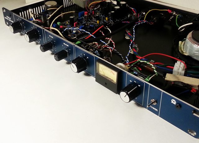
1176 Rev D in a blue 1u.  Case done a Front Panel Pros which are a bit less than FPE if you are mindful. I already had several 'normal' looking 1176s and needed the space.
Thanks Mike
gGZu068l.jpg

Great build guide and great project as you obviously know. 
Cheers
Dylan
 
Hairball Audio said:
I would test for continuity Between the parts.  That AC maybe maybe unrelated to the parts.

Thanks Mike! You're right, there's no continuity between both parts :) I even didn't thought about that :D Two metal parts screwed together, so why i should check that :D Sometimes obvious things aren't so obvious ;)
 

Latest posts

Back
Top