[BUILD] 1176LN Rev D DIY

GroupDIY Audio Forum

Help Support GroupDIY Audio Forum:

This site may earn a commission from merchant affiliate links, including eBay, Amazon, and others.
Happened to fit the top panel finally!
There are still minor noise issues to fix but I’m quite happy!

The extra features are just a switch to reverse the order of compression and eq, and another rotary to send the sidechain through a high pass or to send it to the eq circuit.

Frontpanel made from frontpanels.de from a inkscape design I’ve drawn.

Cheers!
 

Attachments

  • 6F3BADB3-A0B2-4779-B384-7C9A2CF6064C.jpeg
    6F3BADB3-A0B2-4779-B384-7C9A2CF6064C.jpeg
    1.6 MB
Alexwfm said:
Happened to fit the top panel finally!
There are still minor noise issues to fix but I’m quite happy!

The extra features are just a switch to reverse the order of compression and eq, and another rotary to send the sidechain through a high pass or to send it to the eq circuit.

Frontpanel made from frontpanels.de from a inkscape design I’ve drawn.

Cheers!

Nice!
 
I've got my stereo build of this about 95% working now but have a few kinks to sort out. I can do most of the calibrations and get it to compress well, all transistor voltages are good but I seem to be getting high gain at the input  stage. Is there an expected AC voltage output for a 0dbu 1k sine at input and controls at 12?
I built my own stepped t-pad for the inputs and think they might be the problem though they seem to be working, as in the volume increases as I would expect as I rotate the switch. With a 0dbu 1k sine at input and controls at 12 I get ~14VAC on one and ~20VAC on the other. I've swapped t-pads between boards and the difference seems to be from them so I'm going to take a look at them again but is that higher than expected? If I turn the ins/outs past 12 the noise floor is very noticeable.
I know there's a lot of variables including  gain staging etc. but wanted to ask.

edit: I found a loose connection on one of the t-pads and the outputs are even now but still about 13VAC when loaded which is much higher than it should be according to the hairball troubleshooting guide.  Guess I'll just work my way through until I figure it out.
 
I've had some trouble getting my meters to zero since I built a stereo version (on the old boards) and I wanted to try to fix things. The problems are definitely related to my meter drivers since everything works properly in +4 mode. My compression has always worked properly as well.

Going off the schematic here:

http://library.hairballaudio.com/docs/fet_rack_d_doc_v1.11.pdf

I shrank R72 to about the same size as its companion and I got pretty close, with a little extra slop. I still wasn't able to get 0V across R74. So I made it smaller (down to about 500R now), and I was finally able to zero it. I left the righthand channel the same as it was before.

But I can't get the calibration step to work properly anymore. My meter in GR mode barely jumps when I switch the bypass on and off, regardless of the compression ratio (mine goes all the way down to 2:1 with a much lower threshold as well).

What exactly are the consequences of changing R72? It looks to me like it's just a limit on the voltage divider created by the 0 pot, but does it affect the actual meter driver at all? Is there some other place I should be looking to fix these issues (either the inability to zero or the seemingly weak needle bouncy bouncy)?
 
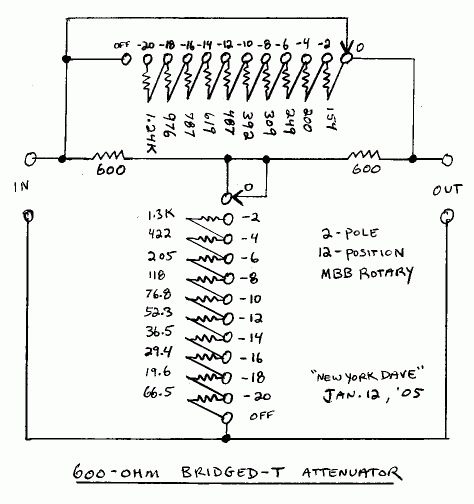
Alright so I'm pretty sure my stepped t-pads are the problem with my gain problem. I built them myself according to this schematic
bsjkjfH.gif

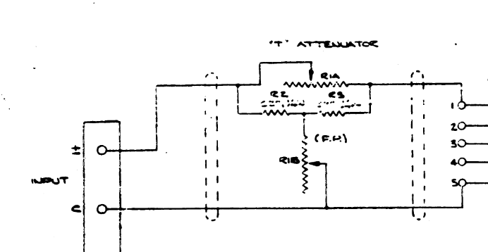
I've just looked at how it was drawn in the original schematic and seems to be slightly different
Igb4LXp.png

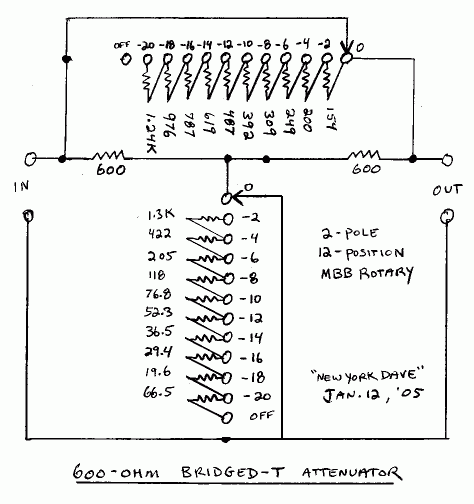
Maybe it's just a bad scan but it looks like the left hand end of the top pot is not connected to the wiper, the bottom pot doesn't have it's bottom end connected to the com and the wiper is connected to the opposite end. I drew a altered version below
irpiCzw.gif


Anyone know if that's how it should be?

Edit: I tried a few different ways or wiring it and none of them worked so I'm thinking I had them right the first time. I've found that if I send it a -10dbu signal from my interface the noise floor is much lower and more usable. There must be something wrong regardless but it's at least usable that way.
 
Hello,

My 1176 (old rotary version) doesn't compress, only INPUT and OUTPUT seems to have an action on the signal.
What can I check first to debug it ?

Thanks,
 
babaorum said:
Hello,

My 1176 (old rotary version) doesn't compress, only INPUT and OUTPUT seems to have an action on the signal.
What can I check first to debug it ?

Thanks,

Most off this stuff applies:
https://www.hairballaudio.com/blog/resources/post/fetrack-troubleshooting-guide

Likely a Pad 22/21 issue.

Mike
 
I'm working on a Rev D V2.2 board and having some issues. All the voltages are reading fine except for the GR Meter Driver section, which is way off, and I can't get the Q Bias control to decrease the level when trying to calibrate. I tried searching through this thread and doing the usual stuff (reflowing solder, checking component values, etc), but no luck. Maybe when someone sees these wacky voltages, they'll know what the issue is (bad Q11 FET maybe?).

Q11:
D: 24.8V
S: -6.3V
G: -5.0V

Q12:
B: -6.3V
C: 24.8V
E: -2.0V

Q13:
B: -1.15V
C: -1.77V
E: -1.78V

If it makes any difference, my B+ is a hair low at 29.8V. Any help would be super appreciated.
 
Harpo said:
if voltage readout was correct, I'd expect a broken or wrong part or Q12 placed with wrong orientation and now broken because of this.

Thanks Harpo. It turns out I made a bone-head mistake and switched wires 18 and 20. The voltages all read correctly now (or close enough).

I'm having another issue now though - I can't seem to get my meter to work.

It's an old vintage meter that I like the look of, but it's a DC meter, and it reads  0dB at around 110mVDC. I built a half-wave rectifier for the output, and it reads that well enough, but it doesn't react at all in GR mode (doesn't go to "0," doesn't move).

I'm assuming the output of the GR meter circuit is DC and doesn't need to be rectified (I'm reading DC across points 28 & 29). When have the meter set to +4/Output, I read 1.1VDC across 28 & 29, but when I switch into GR mode, it drops to 0VDC.  It's almost like the meter is loading down the driver circuit. I measure around 300 Ohms across the meter pins. Is that too low? Does the GR meter signal voltage have to be buffered or something?
 
More experimenting. I built a FWB rectifier for the meter (which seems to be a 300uA DC meter), and get pretty close to 0dB at 1.223V with a 3K6 resistor. All good on the output metering.

The GR metering still isn't working though. When switched into GR mode, I measure around 300mV across points 28/29, which feed the meter in that setting, but see nothing on the meter (doesn't go to "0," stays at -inf). It shouldn't matter with a FWB rectifier, but I checked the DC polarity, and it's correct. I'm at a loss now.

This is a DC meter, but I can only get it to read AC (with a rectifier), and it doesn't seem to be reacting to the DC  coming from the meter driver circuit. Any ideas?
 
Harpo said:
Did you already replace the broken Q12 ?

No, once I switched the wires I had reversed, the voltages all settled down to be close to the ones on Mnats labelled schematic  (http://mnats.net/files/1176REVD_VOLTS.pdf).

Do you think Q12 could have been damaged if it’s now reading the correct voltages?
 
OneRoomStudios said:
Do you think Q12 could have been damaged if it’s now reading the correct voltages?
From your 
Q12:
B: -6.3V
C: 24.8V
E: -2.0V
you have exceeded the 30 VCEO abs.max.rating of the 2N3707.
Considering your not correctly working circuit, assuming this part to be blown isn't this far off, but YMMV ...
 
Harpo said:
you have exceeded the 30 VCEO abs.max.rating of the 2N3707.
Considering your not correctly working circuit, assuming this part to be blown isn't this far off, but YMMV ...

You're right, it was worth a shot. I replaced it, but get the same readings as before and the meter is still not working. The circuit appears to be loaded down by the meter.
 
Progress.

I got a new meter. I can now get the meter to zero when I bypass R44, but not when it's in circuit. I read that occasionally a 2K trimmer isn't enough to get it there, depending on the JFET, so I replaced it with a 5K, and I'm closer....but still not there. I can only get the meter to around -1.25dBVU at the extreme end of the 5K trim. Should I order a 10K trimmer and see if that will get me there, or should I be looking for some kind of issue that's causing the problem?
 
One other thing to confirm. I'm building the rotary version, but not using the rotary meter board (only the rotary ratio board). Instead, I'm using a DPDT toggle for the meter (either GR or +4 output), and a SPDT for Bypass. I believe I have the bypass switched wired correctly, but now I'm questioning myself. In bypass, pin 22 is shorted to ground, and when not bypassed, pin 22 is connected to pin 4 from the rotary ratio board. Is that correct?
 
Hi guys, first post here and a complete newbie to DIY. I am starting my second hairball 1176 and I already have a utc o-12 and a UA 5002. After gathering as much info as I could I'd really appreciate it if someone could double-check my findings as far as wiring the transformers goes. so here it goes:
- utc pin1 to pcb pin1
  utc pin5 to pcb pin4
  utc pin6 to pcb pin5
  utc pin8 to pcb pin8
  utc pin3 to pcb pin7

i am assuming that where the dot is on the pcb its pin 1 and then? clockwise or anti clockwise for consecutive numbers?

As far as the output I see that UA has the same color wiring as EA correct?

Thanks in advance.
 
Hi all, apologies if something similar has been addressed in the thread- at 270+ pages it's a bit of a read and I haven't found anything in searches.

I've had a Mnats 1176 for years that has been operating correctly with no issues.
I recently bought a half finished kit from someone who ran out of time to finish it, and have been having nothing but trouble getting it to operate correctly.
It passes signal and compresses, however level is considerably lower than on my other working 1176- often 12 to 20db lower with identical signals.

I've tried the following to rectify the issue:

- swapped t-pad with known working
- swapped input tx with known working
- replaced full PCB (I had a spare stuffed one, so used this. I haven't replaced the meter or ratio boards)
- checked all resistors and other parts visually
- checked voltages (all within 5% of each other)
- replaced 0 set (it was an incorrect pot, but I can't imagine this would effect anything)
- checked and rechecked all wiring
- confirmed output pot is correct spec (again, about 5% out of tolerance with my other unit, but fine)

The only elements that have remained consistent are the output tx, power tx, ratio and power boards, and the 2N5457 JFETs as I didn't have spares of those.

As the issue is present even with compression off, I'm assuming it has to be occurring in the preamp or line amp, and as the metering is showing this signal as significantly lower I'm assuming it has to be in the preamp PRIOR to signal being passed on to the meter circuit. As I've swapped out the PCB, I've essentially replaced all parts in the preamp, with the exception of Q1, one of the 2N5457 JFETs.

Is it possible for Q1 to be having this much impact on gain? 

Thanks in advance.
 
Alistair said:
Hi all, apologies if something similar has been addressed in the thread- at 270+ pages it's a bit of a read and I haven't found anything in searches.

I've had a Mnats 1176 for years that has been operating correctly with no issues.
I recently bought a half finished kit from someone who ran out of time to finish it, and have been having nothing but trouble getting it to operate correctly.
It passes signal and compresses, however level is considerably lower than on my other working 1176- often 12 to 20db lower with identical signals.

I've tried the following to rectify the issue:

- swapped t-pad with known working
- swapped input tx with known working
- replaced full PCB (I had a spare stuffed one, so used this. I haven't replaced the meter or ratio boards)
- checked all resistors and other parts visually
- checked voltages (all within 5% of each other)
- replaced 0 set (it was an incorrect pot, but I can't imagine this would effect anything)
- checked and rechecked all wiring
- confirmed output pot is correct spec (again, about 5% out of tolerance with my other unit, but fine)

The only elements that have remained consistent are the output tx, power tx, ratio and power boards, and the 2N5457 JFETs as I didn't have spares of those.

As the issue is present even with compression off, I'm assuming it has to be occurring in the preamp or line amp, and as the metering is showing this signal as significantly lower I'm assuming it has to be in the preamp PRIOR to signal being passed on to the meter circuit. As I've swapped out the PCB, I've essentially replaced all parts in the preamp, with the exception of Q1, one of the 2N5457 JFETs.

Is it possible for Q1 to be having this much impact on gain? 

Thanks in advance.

This will still apply to older boards:
https://help.hairballaudio.com/hc/en-us/articles/360045942974-FET-RACK-Troubleshooting-Guide

And will help you find exactly where the error is.

Mike
 
Back
Top