[BUILD] 1176LN Rev D DIY

GroupDIY Audio Forum

Help Support GroupDIY Audio Forum:

This site may earn a commission from merchant affiliate links, including eBay, Amazon, and others.
Doooohhhh! finally found the bad solder joint..
all is good, the board works great ( I must add that I am not fond of the black boards, I find being able to shine light through the boards a very useful troubleshooting technique)
the moral of the story is,: check, check and re check. if it is not working, it is your own fault :oops:
 
[quote author="nielsk"]( I must add that I am not fond of the black boards, I find being able to shine light through the boards a very useful troubleshooting technique)[/quote]
That's probably more to do with the rather opaque solid copper ground plane on one side of the board than with the color of the solder mask, BTW.

JDB.
 
ahhh, so kimosabe'
that does make sense, and I'm sure the build is easier and the board smaller because of the use of the ground plane on the top side. It is still much easier to see traces (and faults) on the translucent green boardstock
 
[quote author="nielsk"]It is still much easier to see traces (and faults) on the translucent green boardstock[/quote]
Absolutely. Debugging a design (or even debugging your assumptions about a design) can be made easier by the Insta-XRay view that you get by holding the board up to the light. Just wanted to point out that in this particular case...

JDB.
 
Sorry if it has been asked but finding a 2200uf 35v for (C24) is driving me nuts. :sad:

That's a BIG cap for a small spot on the PCB.

Will a 1000uf be sufficient for (C24):?:
 
hi kevin,
i can't remember what I used, but if space is tight I usually go for Panasonic NHG lytics. usually, they are smaller (height and most times OD).
what's the pin spacing and OD of the footprint on the Rev.D board?
-grant
 
[quote author="dissonantstring"]hi kevin,
i can't remember what I used, but if space is tight I usually go for Panasonic NHG lytics. usually, they are smaller (height and most times OD).
what's the pin spacing and OD of the footprint on the Rev.D board?
-grant[/quote]

OD = 13mm
LS = 5mm

VERY small for a 2200u @ 35v :?
 
[quote author="mnats"][quote author="pH"]Quick question about using the input transformer board with the Altran: if I'm reading the board correctly I need to link B to C, and E to F, yes?[/quote]
revd_trx_brd.gif

Yes, that's what I put at the bottom of the board.

That means pins 6 and 7 will be connected to the ground plane.

On the Altran, pin 6 goes to the can. On the Cinemag CMLI-15/15PCA (a 1:1 transformer not explicitly shown, but that shares the same footprint and pin 1 assignment) pin 6 goes to a shield and pin 7 goes to the can. It wasn't easy trying to fit all the information at the bottom of the board, so even though it says to connect the two links, only one is going to the can with the Altran.

[quote author="pH"]Can't find a pinout for the C-3837-1 so I'm wondering what's happening here.[/quote]
C-3837-1.gif

I've now linked to it from my Rev D page. Here it is courtesy of Ed.[/quote]

I'm assuming that Pin 7 on the ALTRAN is a dead/open Tap & doesn't connect to anything inside :?:
 
[quote author="khstudio"]
OD = 13mm
LS = 5mm

VERY small for a 2200u @ 35v :?[/quote]
For what it's worth I used a Nichicon UVZ1V222MHD . The screen printed outline isn't there to dictate how big a cap you can use; there is enough room for a 16mm diameter cap where C24 goes...
[quote author="khstudio"]I'm assuming that Pin 7 on the ALTRAN is a dead/open Tap & doesn't connect to anything inside [/quote]
Got a multimeter? :wink:
 
hi kevin,
looking at the overlay i think i remember now that i bent the legs for both C26 and C24 at right angles having the bodies of the cap move out towards the edge of the board to allow room for both caps. not the most steady for the caps, but you can zip-tie the two caps together once they are soldered in for a little more stability. looking at my build pics i think i used PWs! :shock: :grin:
regards,
grant
 
hi luis,
you can use the 2K trim pot, it won't hurt anything. it's a multi-turn trim pot so you should still be able to dial in whatever resistance you'll need fairly easily.
regards,
grant
 
mnats said:
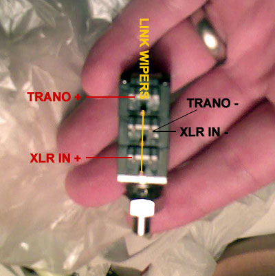
OMFG, still having problems wiring the T Attenuator? Labbie Neeno drew a nice picture for you.

This link appears to be dead.  Does anyone have the actual link or diagram?  I'm using a Mallory 600 ohm T-Pad and I'm a bit confused exactly how to wire it up to the board.  Yes, yes, I have read over the thread for many hours today but many links appear to be dead, and the search function seems to not be as usable as before.

Thanks!
Sig

 
matta said:
Thanks!

This may help others visualize it.

1176_attenuator.jpg


Sorry about the bad quality of the pic... cell phone camera was all I had handy.

Cheers

Matt

The Mallory T-Pad appears to have the identical layout to this pic - can anyone please confirm if I can wire it in the same fashion?

Thanks!
Sig
 
Siegfried Meier said:
This link appears to be dead...and the search function seems to not be as usable as before.
Link is fixed now, but it refers to a bridged T pad that some people have been using.

I was able to find neeno's post in five seconds flat with the new forum's search function, so thanks to Ethan for our upgrade.

Didn't your Mallory come with a diagram? Mine did.
 
Yep, I found the new link too while going through the entire thread - spent 6 hours yesterday reading every tidbit.  My Mallory's did not come with a sheet.  When I saw this new T-Pad, it looked very similar so I just assumed it would have the same connections.

Thanks!
Sig
 

Latest posts

Back
Top