[BUILD] 1176LN Rev D DIY

GroupDIY Audio Forum

Help Support GroupDIY Audio Forum:

This site may earn a commission from merchant affiliate links, including eBay, Amazon, and others.
Thanks a lot for your help guys, I really needed it!. Still one more question..
I've got a rotary version Purusha case and under the VU meter(s) there'a hole for a switch that says : bypass/comp. I'm sorry but I can't find it when I look at the schematic, and how should I connect the dual/link switch.... still a bit confused here...sorry..
Best Regards , Jyrki
 
That hole is redundant on the Parusha case. The bypass/comp switch is already on the meter board. You could possibly use it for a stereo link jack or external sidechain later down the road.

John
 
Hi guys,
i am building a 1176 REV D with Mnats boards (ver 1 ),
and couldn't find the wiring for the input transformer board,
i am using Altran tranny and Mallory T600 attenuator,
I looked at Skylar wiring pdf file, manats 1176 revD pdf, hairball pdf,
searched across the long thread, but didn't find the info,
can someone help me ?
Best regards,
pacemaker
 
Big thanks you guys for your input and help!!! ....about that stereo link option, there IS already a hole for a dual/link switch on purusha-case faceplate???
I still cant find info how to wire that switch?
Best Regards, Jyrki
 
OK, Thanks, I'll have to think about that option. By the way, I use sifam al19-retro VU meters for this project and I think there' a 12 volt@20mA Led illumination backlight.....
What would be the best way to supply 10-12V for those meter-lights. I use the mnats external PSU but I'm not sure how to connect the meter lights.... maybe a really dumb question but....???
Best Regards,Jyrki
 
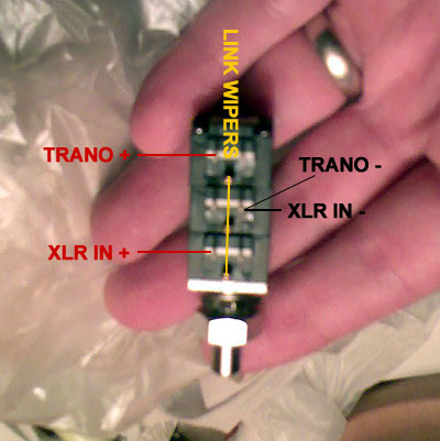
Thanks for your info! Has anyone used the 3 deck attenuator(Hairballaudio), I'm going to use it('cause haven't got a 2 deck ver.)but cannot find any wiring diagram? I would greatly appreciate your info!

  Jyrki3101
 
jyrki3101 said:
Thanks for your info! Has anyone used the 3 deck attenuator(Hairballaudio), I'm going to use it('cause haven't got a 2 deck ver.)but cannot find any wiring diagram? I would greatly appreciate your info!

 Jyrki3101
I've used Hairballs 3 deck attenuator and it has been great for the 1176 rev D.
tpad2.jpg


This one isn't my build but was a reference I used when I was building mine.
tpad.jpg
 
pacemaker said:
Hi guys,
i am building a 1176 REV D with Mnats boards (ver 1 ),
and couldn't find the wiring for the input transformer board,
i am using Altran tranny and Mallory T600 attenuator,
I looked at Skylar wiring pdf file, manats 1176 revD pdf, hairball pdf,
searched across the long thread, but didn't find the info,
can someone help me ?
Best regards,
pacemaker
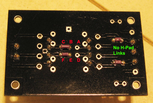
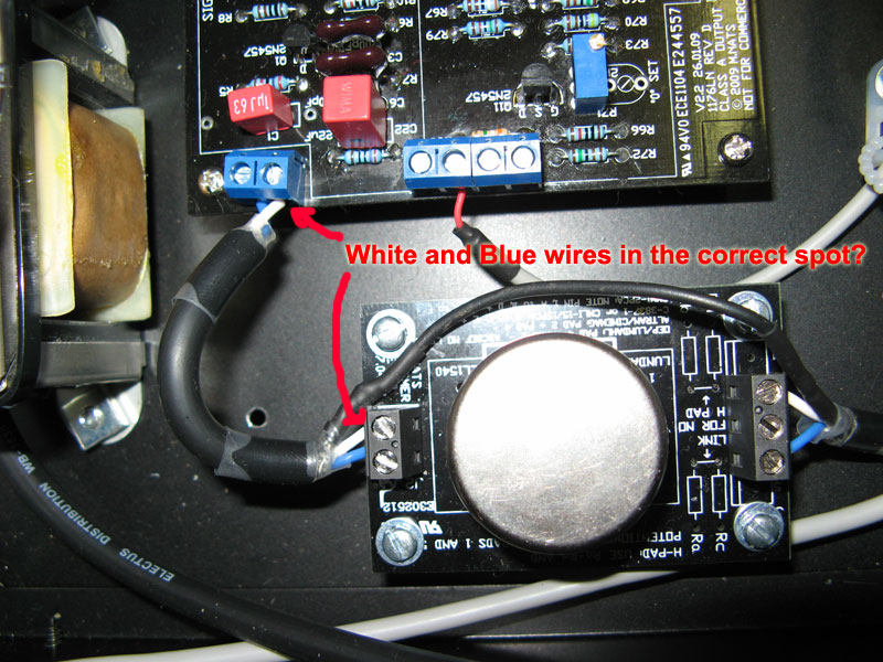
Im not sure if Mnats changed the way the board works for the rev D version 2 I had, but this was the wiring for my board.

altranLinks.jpg


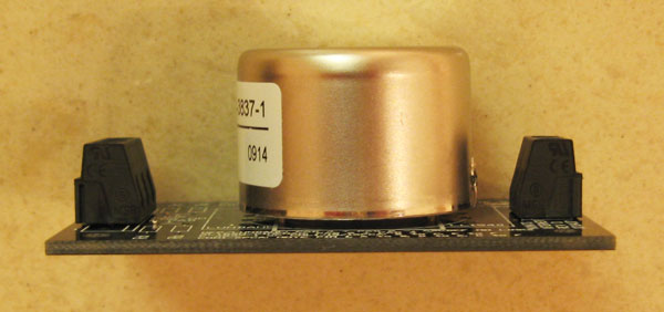
Leave a space on the underneath of the Altran. Also look at the way the label is facing and the little solder thing on the Altran case at the right of this pic as an assistance to which way to mount it on the board.
altranLinks2.jpg


This is the wiring I did that worked.
wireCheck1.jpg
 
Quick question:

Using the input attenuator and pcb from hairball and looking at Skylar's wiring guide, do i need to include the 620 ohm resistors on the attenuator still? If so, how is it wired on hairball's attenuator?

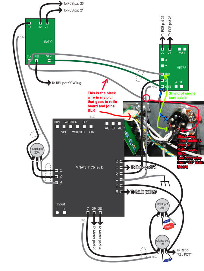
Also, on Skylar's diagram, xlr pin 1 (for example. There are a few other wires labeled as such as well) has a long wire that says NC. I am guessing thats Not Connected. Why are the wires drawn in if they aren't connected to anything...? Or am i misunderstanding something?

Thanks!
 
the resistors aren't needed on hairballs attenuator.  You are right about the "NC" wires.  I guessed that it might still help lower the noise since the ground is connected through the input transformer.  I could be wrong though.  I never tested it without it
 
The wires labelled "N.C." are not connected at one end, but tied to ground at the other end, or to another wire that itself travels to ground, and should be the shield of another wire.  For instance, the wire travelling between pad 22 on the main board and pad 22 on the meter board should be a shielded one, with its shield attached at the main pcb to the adjacent ground pad, but cut short as close to the meter pcb as possible, with shrink wrap or some other precaution in place to avoid shorting things.  Looks like his shields are all grey in his diagram.  Hope that helps. 
 
bdubya said:
The wires labelled "N.C." are not connected at one end, but tied to ground at the other end, or to another wire that itself travels to ground, and should be the shield of another wire.  For instance, the wire travelling between pad 22 on the main board and pad 22 on the meter board should be a shielded one, with its shield attached at the main pcb to the adjacent ground pad, but cut short as close to the meter pcb as possible, with shrink wrap or some other precaution in place to avoid shorting things.  Looks like his shields are all grey in his diagram.  Hope that helps. 
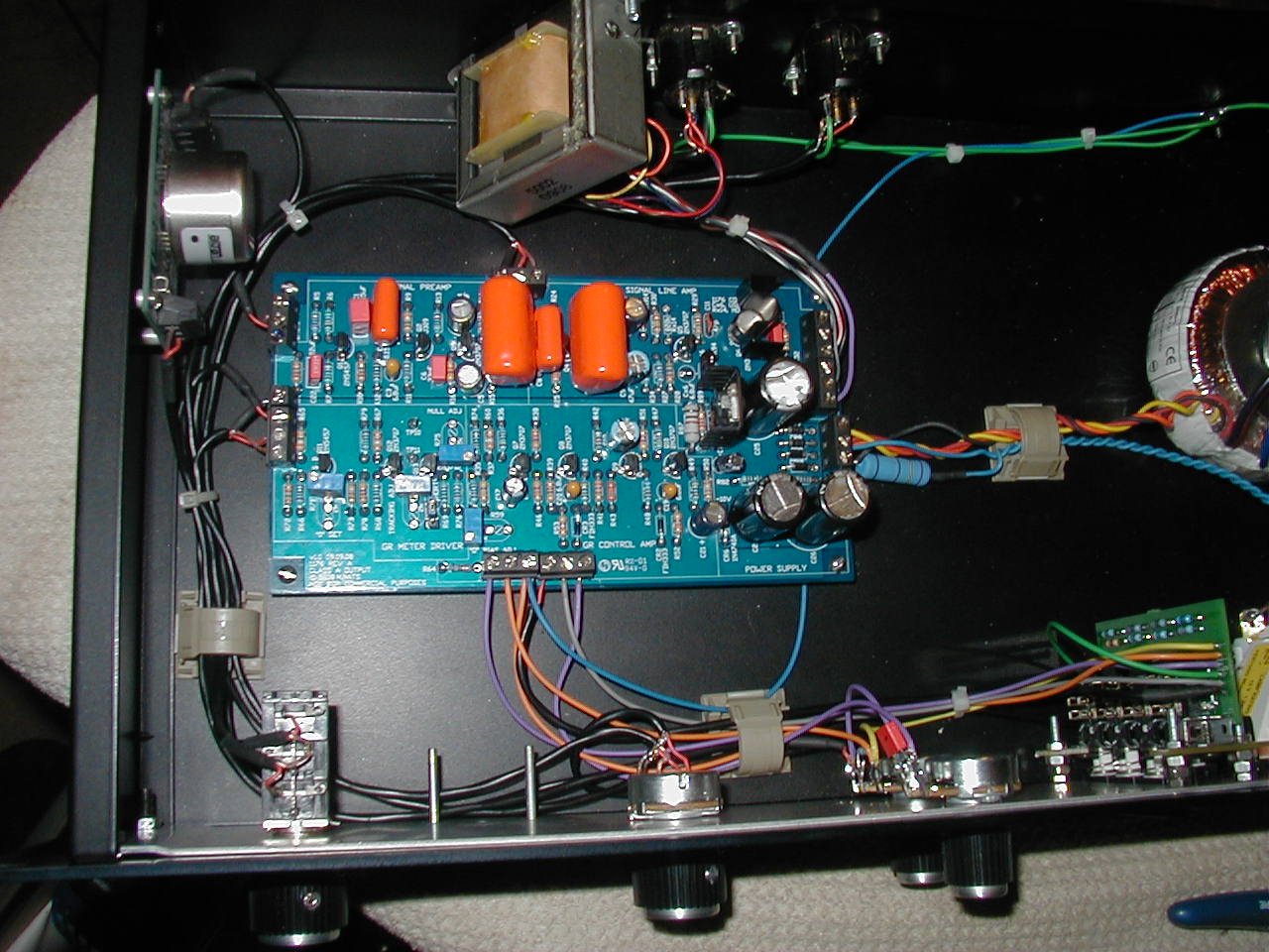
I wired that section like this, which is correct from what I recall.

wireCheck3.jpg
 
Hi, I started measuring transistor voltages, I think I have a serious problem, The very first measurement with Q6(2n3053) B(2.73v) C(27.3v) E(2.23v) / Q5 :    B(3,2v), C(25.6v) E(2.7v)   /  Q4 : B(1.02v) C(4.15v) E(0.45)
 
  ,  have I wired my O/P transformer( HBaudio UA5002) wrong. I followed Skylars wiring diagram since I have mnats pcb's and CONNECTED those yellow/orange wires together,like I was adviced to do on this thread. Well, Although a signal is passing through and compression happening, front panel controls are affecting the signal and VU meter reacts also??
. I have checked everything else in the signal line amp: resistor values all caps, and exact 30V on the O/P transformer primary's black wire!
This is somethin really weird, so I would greatly appreciate of any kind of help!    ....I can't figure this out by myself!
Regards jyrki3101
 
hi guys! my 1176 is working great, never had a problem with the circuit.

i have a problem with the meter instead: i do all the steps of the calibration and the meter goes to zero (almost),
after a couple of weeks the meter is 1/2 db off, i mean it goes not to zero, just -1/2 db.

this thing makes me mad, is it normal?
 
Hello Pietro
For me it was normal,
I had to add a mini potentiometer  on the front  panel for of the zero calibration ...
 

Latest posts

Back
Top