


astrovic
Well-known member
Hey guys - don't post here often but have got some valuable info from this thread and the Rev A thread while building this is baby, a dual 1176 with a Rev A and a Rev D:
Front (you can see the dual G1176 I built a couple of years back in the background):
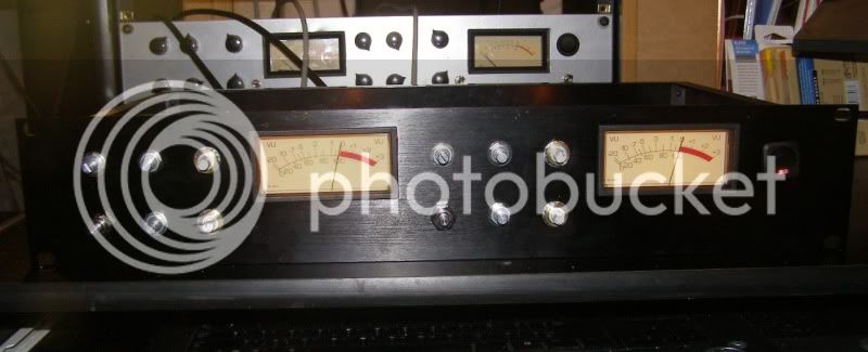
Rev A on the left, Rev D on the right:
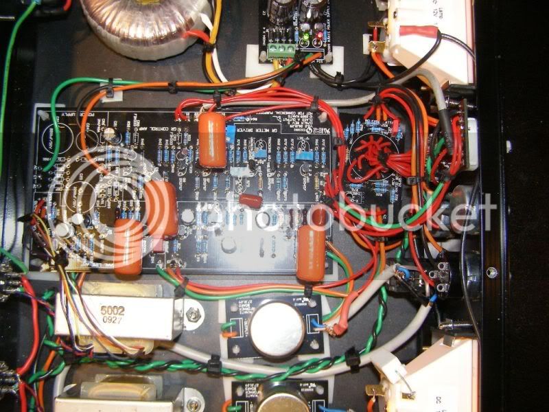
Rev A:
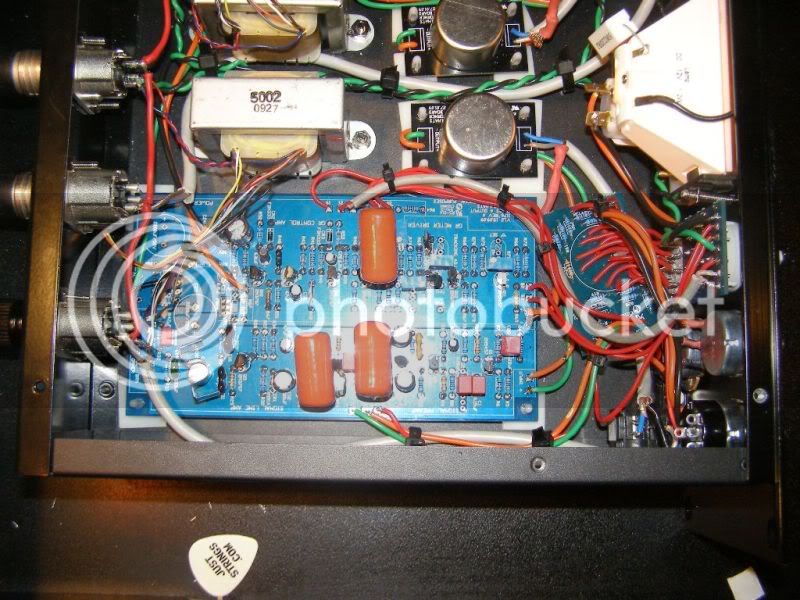
Rev D:
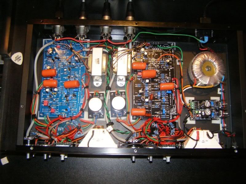
Due to the tight space, I mounted the ratio boards in the floor and ran jumpers to the ratio switch. This made front panel work easier, but added a lot of wiring!
I managed to keep the nuffiness to a minimum - just a couple of stupid mistakes that IO slowly cottoned on to. I've been building long enough now to know that there's a 98% chance of human error causing the problems, so I just keep searching until I find the mistake! Works nearly every time.
I'm down to 2 issues:
1. Calibrating the meter in GR mode is proving a challenge on both units. I'm burned out on this build, so I'm going to park that issue for a while and come back to it later when the head is refreshed
2. I only ordered one bloody To-5 heatsink for the output transformer. Dag-nammit! You can see that the 2n3053 in the Rev A has the Flying Nun outfit on, but the Rev D is a nude dude. If any Aussies out there happen to have a TO-5 style heatsink that is surplus to requirements, I happily grab it Otherwise it's a special order to Futurlec or Ebay or whatever, which is fine and will happen if necessary but a bit of a pain as I'm not planning on ordering anything else.
What can I say about this fella? Mnats, you are a champion. This board is an absolute delight to work with, a real work of art. The effect you've put in leaves me speechless. And both units sound unbelievable - you haven't heard how rich and warm a 1kHz sine wave can sound until you've put one through these puppies!
Front (you can see the dual G1176 I built a couple of years back in the background):
Rev A on the left, Rev D on the right:
Rev A:
Rev D:
Due to the tight space, I mounted the ratio boards in the floor and ran jumpers to the ratio switch. This made front panel work easier, but added a lot of wiring!
I managed to keep the nuffiness to a minimum - just a couple of stupid mistakes that IO slowly cottoned on to. I've been building long enough now to know that there's a 98% chance of human error causing the problems, so I just keep searching until I find the mistake! Works nearly every time.
I'm down to 2 issues:
1. Calibrating the meter in GR mode is proving a challenge on both units. I'm burned out on this build, so I'm going to park that issue for a while and come back to it later when the head is refreshed
2. I only ordered one bloody To-5 heatsink for the output transformer. Dag-nammit! You can see that the 2n3053 in the Rev A has the Flying Nun outfit on, but the Rev D is a nude dude. If any Aussies out there happen to have a TO-5 style heatsink that is surplus to requirements, I happily grab it Otherwise it's a special order to Futurlec or Ebay or whatever, which is fine and will happen if necessary but a bit of a pain as I'm not planning on ordering anything else.
What can I say about this fella? Mnats, you are a champion. This board is an absolute delight to work with, a real work of art. The effect you've put in leaves me speechless. And both units sound unbelievable - you haven't heard how rich and warm a 1kHz sine wave can sound until you've put one through these puppies!


![Soldering Iron Kit, 120W LED Digital Advanced Solder Iron Soldering Gun kit, 110V Welding Tools, Smart Temperature Control [356℉-932℉], Extra 5pcs Tips, Auto Sleep, Temp Calibration, Orange](https://m.media-amazon.com/images/I/51sFKu9SdeL._SL500_.jpg)


