You are using an out of date browser. It may not display this or other websites correctly.
You should upgrade or use an alternative browser.
You should upgrade or use an alternative browser.
[BUILD] 1176LN Rev D DIY
- Thread starter mnats
- Start date


Help Support GroupDIY Audio Forum:
This site may earn a commission from merchant affiliate
links, including eBay, Amazon, and others.

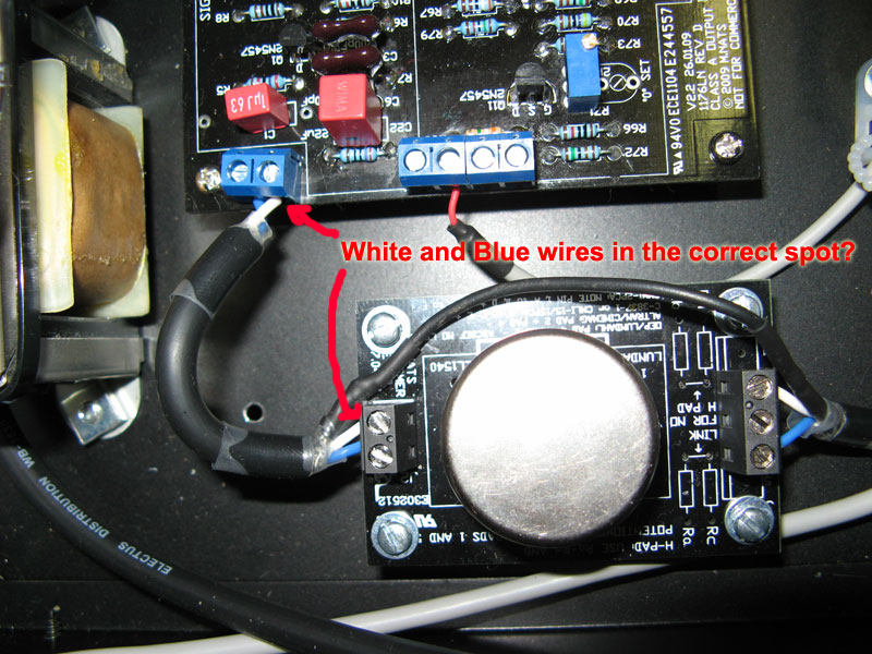
Wiring for the Altran on the Rev D version 2. Mine is a mono unit.benlindell said:I have a question regarding using the old h-pad boards, I found the talking about it on about page 15 but all the links and images are dead, anyone have some info on how to hook these up?
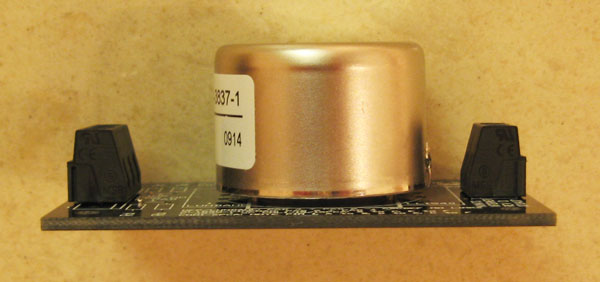
Leave a space on the underneath of the Altran. Also look at the way the label is facing and the little solder thing on the Altran case at the right of this pic as an assistance to which way to mount it on the board.
This is the wiring I did that worked.
benlindell said:I have a question regarding using the old h-pad boards, I found the talking about it on about page 15 but all the links and images are dead, anyone have some info on how to hook these up?
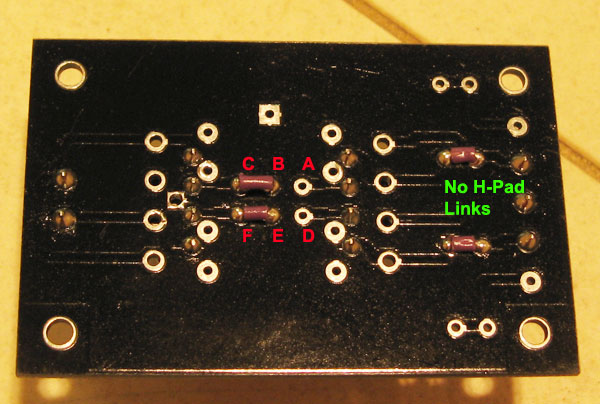
Not sure where the W'OB thread went, but IIRC he described and drew something like the first image that currently comes up with this search (link appears dead but squint and you can read the cached image) using - interestingly - unequal resistors on either side of the pad. The instructions are right there on my boards though - you fill the Ra to Rd with resistors, leave out the "NO H PAD" links and hook up a rheostat-wired potentiometer between pads 1 and 5.
You'll have to play with the values but you may be able to calculate something to get you in the ballpark or use one of the various online calculators. Give it a try and report back.
Or maybe someone out there has one of the dual 1176 thingies that has this input configuration and could read off the component values?
benlindell
Well-known member
Ok, but if I want to use a tpad attenuator I just hook it up like canidoit's pictures correct?
benlindell said:Ok, but if I want to use a tpad attenuator I just hook it up like canidoit's pictures correct?
It's impossible to say without knowing what is going on at the T pad, but the if the color coding is meant to indicate the + and - it is incorrect. Working and correct can be two different things; without having a look at the input and output from the XLR to the board of the previous pictured unit on an oscilloscope you wouldn't know if the polarity is reversed or not.
Have a look at the new Rev A schematic I've been working on noting the numbers of the transformer pins:
The pins of the Altran are numbered clockwise from the bottom view sort of like an IC.
If you aren't using the Altran you will have to refer to your particular transformer datasheet. That is one reason why the polarity of these early boards is not marked, while the current ones supplied by Hairball - which are only designed for the Altran - are.
ChrioN
Well-known member
For those of you who got the VU meters from hairball, with the 12v 1.2w lamp: from where did you get the juice for the lamp?
directly after the 7824? after the rectifier? neither?
directly after the 7824? after the rectifier? neither?


![Soldering Iron Kit, 120W LED Digital Advanced Solder Iron Soldering Gun kit, 110V Welding Tools, Smart Temperature Control [356℉-932℉], Extra 5pcs Tips, Auto Sleep, Temp Calibration, Orange](https://m.media-amazon.com/images/I/51sFKu9SdeL._SL500_.jpg)


Biasrocks
Well-known member
ChrioN said:For those of you who got the VU meters from hairball, with the 12v 1.2w lamp: from where did you get the juice for the lamp?
IIRC 5w or 10w ~ 220 ohm resistor off the secondary of the PT.
Mark
benlindell
Well-known member
mnats, would you happen to still have the photos around that accompany this post: http://www.groupdiy.com/index.php?topic=20058.msg246397;topicseen#msg246397
I believe I have some of these boards.
I believe I have some of these boards.
benlindell said:mnats, would you happen to still have the photos around that accompany this post: http://www.groupdiy.com/index.php?topic=20058.msg246397;topicseen#msg246397
Links restored. The photos were all moved to my new domain but somehow the post didn't get modified to link to them.
benlindell said:I believe I have some of these boards.
I have no record of you buying the old Rev Ds but maybe you got them from someone else?
benlindell
Well-known member
thanks for the photos. I bought my boards from API, unstuffed and they had the mod already done on Q7-10. I also put the correct values in for r15 and r64. I set the q bias just fine but when listening to it as soon a signal hits the threshold it goes crazy with the gain reduction, any ideas what may be causing this? I have 2n5088s in q7-q10 and 3707s in q5, q12, q13, could that cause this?
benlindell said:I set the q bias just fine but when listening to it as soon a signal hits the threshold it goes crazy with the gain reduction, any ideas what may be causing this? I have 2n5088s in q7-q10 and 3707s in q5, q12, q13, could that cause this?
As long as the transistors were matched for beta in the meter circuit and are above 250 hFe in the sidechain it doesn't matter if they are 2N5088s or 2N3707/8s.
I'm hoping someone can help me on this it's my first DIY build... I've been scratching my head for months now. I can't see anything relevant in this thread, but apologies if this kind of problem has been discussed before.
I'm having problems getting the GR circuit working. I've done the Q-Bias calibration a number of times, but I can't hear any compression. With the scope I can see that the GR circuit is outputting something. You get "half-wave"-like peaks appearing once the signal goes above a certain point, so this should be compressing. But there's no audible compression. Strangely, the odd and even peaks in the signal measured at CR2/3 have different amplitudes.
I've taken these measurements with different input vols:
Do these look right? Wrong?
I've checked through the circuit and afaik it's all correct, although I'm wondering whether it is connected up to the ratio board correctly. The unit is wired up following Skylar's guide and the JBL schematics, but I suspect I have got something connected wrongly here. FYI I have hairball's kit.
I'm having problems getting the GR circuit working. I've done the Q-Bias calibration a number of times, but I can't hear any compression. With the scope I can see that the GR circuit is outputting something. You get "half-wave"-like peaks appearing once the signal goes above a certain point, so this should be compressing. But there's no audible compression. Strangely, the odd and even peaks in the signal measured at CR2/3 have different amplitudes.
I've taken these measurements with different input vols:
| Signal | C17 | C19 | C20 | Pad 19 | R55/6 | Q1 |
| AC | AC | AC | DC | DC | AC | |
| -3dB | 0.8V | 0.4V | 1.0V | -0.568 | -0.568 | 0.08 |
| 0 dB | 1.0V | 0.7V | 2.0V | -0.539 | -0.568 | 0.10 |
| +3 dB | 1.2V | 1.0V | 2.5V | -0.464 | -0.568 | 0.12 |
Do these look right? Wrong?
I've checked through the circuit and afaik it's all correct, although I'm wondering whether it is connected up to the ratio board correctly. The unit is wired up following Skylar's guide and the JBL schematics, but I suspect I have got something connected wrongly here. FYI I have hairball's kit.
benlindell
Well-known member
I found my problem, and mathsieve, check to make sure you didn't do the same, I was following the wiring pdf and just re-read hairball audio's pdf and I had connected the grn, blk, and 22 pads on the meter board. As I undid those, I wasn't getting any compression, verify on yours that you have a connection from grn to 22.
So let me get this straight. According to Skylar's diagram, BLK is the ground connection between the meter and ratio board, which then terminates from the ratio board at the ground connection between pad 18 and 22. GRN connects the meter board and the 4th connection on the ratio board. 22 is connected straight to meter board. I'm using the spare switch on the meter board as GR Disable. So I have GRN and 22 connected when the GR Disable switch is not engaged (i.e GR on), and 22 and BLK connected when it is. Either way, I don't notice any audible compression with or without it engaged.
In another, and probably unrelated problem, the whole unit sounds rather 'thin'. There's little bass response below 150Hz. I haven't done a sine sweep of the unit yet, but it's definitely not right.
In another, and probably unrelated problem, the whole unit sounds rather 'thin'. There's little bass response below 150Hz. I haven't done a sine sweep of the unit yet, but it's definitely not right.
benlindell
Well-known member
You only connect blk grn and 22 if you cut the traces on the meter board to use it to display GR, +4, and GR bypass. Not sure where the high pass is coming from, double check your solder joints that always seems to be my problem.
trancedental
Well-known member
Latest update is that after installing new ratio & meter boards & switches on my dodgy 1176D I now have , when engaging the various compression ratio buttons, VU meter working on both the +4 & +8 settings although no VU meter indication happens with the GR (meter buttons) mode button engaged. ??? This is not normal I assume?? 
Also going to install a spdt switch on the attack switch as my existing switch seems a bit dodgy on certain settings : :
So does anyone know a UK or European source for the 25K Attack switch, Farnell don't seem to have any?
Cheers & thanks JK ;D ;D
Also going to install a spdt switch on the attack switch as my existing switch seems a bit dodgy on certain settings :
:So does anyone know a UK or European source for the 25K Attack switch, Farnell don't seem to have any?
Cheers & thanks JK ;D ;D
ChrioN
Well-known member
Mouser got em
ChrioN
Well-known member
For the moment, a 500k pot for the outpot is all I got. I just want to try the circuit out, see if its working properly. Will the circuit work properly with a 500k pot? I can try, but I might get smaller problems caused by the pot. Would be nice to know what small problems the 500k pot could cause
Similar threads
- Replies
- 5
- Views
- 591
- Replies
- 2
- Views
- 562
Latest posts
-

-

-
For Sale FS: Crush'n'blend rev 6 populated board = 75 euro never used
- Latest: andre tchmil
-
-

-
-
-
