


pearldrum944
Active member
- Joined
- Dec 25, 2009
- Messages
- 41
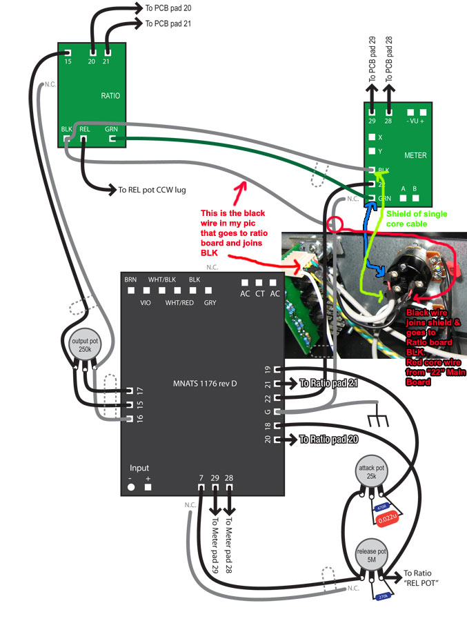
canidoit said:As I understand it, if using the pot switch, nothing from main board 22 and G or Ratio board BLK and GRN goes to the meter board at all. These connections all go to the switch on the pot.
I have wired this using two single connector (plus shield wires).
Do you mean two core cable with shield?
One wire goes from the ratio board GRN (shield connected to ratio board BLK) and then connects to the pot switch with the shield on the upper connector and the main wire (GRN) on the lower connector.
From my pic, the pot solder tabs looks like this.
A B
C
See how A and B have red wires in the pic. Green writing is for the green arrow lines.
Meter GRN -> A (red wire)
Meter BLK -> C (shield)
The shield on this wire is carrying the signal from BLK on the ratio board to the switch.
The shield runs from Ratio BLK -> Meter BLK -> Pot C
The second wire (single core cable with shield) goes from main board 22 and the G pad beside it.
Yes
The shield connects to the G pad.
At the switch, the main wire connects to the common terminal on the switch; the shield connects to the upper terminal of the switch (which also connects to the shield of the other wire, which is connected to BLK on the ration board).
Is this correct? Should I be using a two conductor wire to connect from the switch to the ratio board GRN and BLK? Explain this bit a little further please, what do you mean by switch? Are you talking about the solder tabs at the back of the pot - A B C as I mentioned above?
With the Hairball kit, you are not supposed to use the blk, grn, and 22 connections on the Meter PCB, but connect directly from the ratio PCB, GR bypass switch, and main PCB.
Also, update on my issue... I have compression, +4 and +8 meter settings work, but GR setting only works in SLAM mode. Anyone have an idea?
")


![Soldering Iron Kit, 120W LED Digital Advanced Solder Iron Soldering Gun kit, 110V Welding Tools, Smart Temperature Control [356℉-932℉], Extra 5pcs Tips, Auto Sleep, Temp Calibration, Orange](https://m.media-amazon.com/images/I/51sFKu9SdeL._SL500_.jpg)


