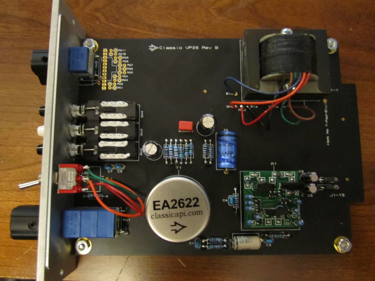
[BUILD] CAPI VP2X~500 Series~Preamp Kit~Official Support Thread

GroupDIY Audio Forum

Help Support GroupDIY Audio Forum:

This site may earn a commission from merchant affiliate links, including eBay, Amazon, and others.
Close Max but you need to stay on ACV. That is the only way you will be able to measure if audio is present. With a source injecting signal, the black probe where it was, probe with the red to all 6 of the solder lugs on SW4. Let me know what you get for each one.

BTW, a mic level input will be very low. It will increase if you check at the + side of C6 due to the gain of the 2622. It will increase more after the DOA if you check either side of C10 (depending on how high you gave the gain pot set). That is the same reading you should get on some of the lugs of SW4.

I myself have never used the iPod/speaker probing method. Only a DMM, scope or an AP.

Best, Jeff
 
Thanks for the directions.. I had a feeling i might be missing it.

I injected signal at J8 and J10 - connected my DMM Black lead to the top lead of R13 and then probed with the DMM Red lead at all 6 of the lugs of Switch 4 - I got no reading on all 6. Not an error reading but nothing.. Maybe a limitation of my DMM? An upgrade wouldn't hurt.

I think i'll change up my signal injection process a bit and perform the readings you noted around C10.

Thanks
Max
 
The module is under power right? You should get signal at 2 of the pins on the Mute switch. You can easily follow the signal from C10 thru the Polarity switch and then over to the Mute switch. Also, a mic level signal needs to be injected. I set me AP to -43dB and 150ohms.

It may be an auto-ranging setting on the DMM. I hear of a lot of that with customers. I had someone recently tell me they got a bad 150k resistor as it read open. Once I mentioned checking the DMM settings, they got it sorted.  ;)
 
Finished mine!  I had one or two solder bridges on the gar2520 that i had to correct.    And then, i had to leave phantom power on and let the pre run for a good 20 minutes before the pops/clicks went away as the DOA 'broke in'.

I tested it on my housemate, using a dynamic (RE20) and a condenser (414B-ULS).  Here's what it sounded like:

http://www.zshare.net/download/9495354277071b4e/ <<< Condenser

http://www.zshare.net/download/949535652b7ced61/ <<< Dynamic


The text message sound during the condenser is Jeff Steiger sending me a text saying "Awesome Job!!"  lolololololol
 
I'm having an issue with my VP26 modules.

I put them in my 51x rack (which works with all my other 500 modules) and when I turn on my power supply, I lose my +-16v rails, and phantom rail. The phantom fuse blows everytime. The 16v fuses don't blow, but they don't put out power either. When I take the VP26 out, I get my 16v power back, and upon changing the 48v fuse, it works as well.

I took out the GAR2520 from a module and put it in the rack where I get phantom working OK, the LED lights up and I don't lose my 48v rail, but the 16v rails still go out.

Any suggestions on what I might check out???

Any key voltage checks? I have rack extenders to use. Since it's both modules, I'm assuming I may have assembled them incorrectly? I followed the guide to a T, and this isn't my first build.

thx
 
Did you add the drain wire to the 48V phantom switch for when it's off? My guess is something with that is wrong. Do you have a pic of that area? Try removing that wire and things should be fine.
 
johnnyscotch said:
...I followed the guide to a T...
The old guide? You saw all the new BOM changes for the Rev B version of the VP26 right? Just making sure.

earl said:
sounds like dead short to gnd make sure the thing is going in the slot right
Could very well be a possible issue. Maybe add a spacer to block the lower 3 pins of the 18 pin connector.
 
Just a quick interjection to share my first ever song recorded with a ClassicAPI VP26 ( it's equal parts VP26 and Sound Skulptor MP73 ).  The vocals were recorded through an SM7b in a home studio then through a VP26/MP73 split that I built (http://www.evolutionarytheory.com/2011/09/classicapi-vp26-and-sound-skulptor-mp73-preamps-are-finished/), and then blended post record to taste.  It was about 50% of each in the end:

http://soundcloud.com/evolutionarytheory/we-jump-lee-safar-featuring

Shameless iTunes plug:
http://itunes.apple.com/us/album/we-jump-single/id475952828

It's very early stages of doing all this stuff at home, so you'll all no doubt be able to get better results, BUT, it's a quantum leap from what I had before, so thanks Jeff for making it possible along with Gary for one kick-ass DOA.
 
Is there a new potentiometer ? Just got up to section 9.1 and noticed mine looks very different. Are there new instructions for this? Thanks!
 
bigevil said:
Is there a new potentiometer ? Just got up to section 9.1 and noticed mine looks very different. Are there new instructions for this? Thanks!
IIRC, your main PCB is green. The t-pad will have a small adapter PCB with it. The proper orientation can be seen here. http://classicapi.com/catalog/product_info.php?cPath=48&products_id=255 The pot's PC pins must be soldered to the adapter PCB. You would bot believe how many people have asked me if it needs to be soldered. Then only 3 jumper wires are required to the main PCB. Notes for that are on the link above.
 
earl said:
sounds like dead short to gnd make sure the thing is going in the slot right

Finally had more time to troubleshoot. This was indeed the problem. Everything is working fine.
It's weird though, it seems to be VERY particular about going in the 18pin slots. More than I would have thought. It has to be pretty much dead-ass dick in there to work properly.

Usually the simplest explanation is the correct one. I was making it more difficult than it needed to be. This was a very easy build and even the GAR2520 was relatively easy, I was really more worried about that than anything.

Thanks for your help guys.
 
Hi, newbie post here.  I recently ordered two vp26 w/ red dots and an A Designs 500hr power supply.  I've previously built two guitar amps from kits (Super Reverb & JTM45) so I have some experience soldering, but am no electronics expert.  The vp26s are the new Rev B.  I double and triple checked resistor/cap values before stuffing the board with the new BOM.  I soldered slowly and thoroughly, or so I thought.

I completed the build after a couple of hours, checked the resistance values between pins of the op amp sockets, but when I tried to test it, no sound at all.  I went back and re-soldered all the pins on the switches because I read those could be trouble areas, as well as the t pad.  Still nothing.  Went back and checked for any visible shorts from but couldn't find any.  Changed cables, mics, etc.  I have no other 500 series to test the rack unit with.

Finally I hooked the vp26 into the line input on another pre amp, a vintech x73, with an sm7b.  If I cranked the line input gain, I could hear my voice with both the preamp and output attenuator all the way open.  The signal was really quiet and distorted, but it raised and lowered with the gain knob and attenuator.  It also muted and decreased in volume with the pad switch.

Tonight, I took it apart and re soldered, reseated the op amp, etc.  Still no luck.  So here I am.  Any troubleshooting advice is greatly appreciated.  I read through this thread, but its been hard for me to translate some of the issues to the new rev b board.  Here are some pictures.  I know the soldering is a little sloppy because I've gone back a couple of times trying to touch things up.

Any help is greatly appreciated.  Thanks so much.

Michael

IMG_1150.JPG


IMG_1145.JPG


IMG_1148.JPG


It is odd that both pre's are acting the same way. After looking briefly over the pics, nothing is jumping out at me. We haven't seen the bottom of the boards but will assume all pins have been solidly soldered.

Since your rack is new and has not been used with other modules, I would look at that next. I have never had that version in front of me but customers have mentioned being able to remove the top from the case to gain easy access to the edge connectors and innards of the rack. You could remove the red dot, insert the module and power the rack. It will be easy to check the voltage at both the -V and +V pins of the opamp sockets. The last one I heard about was between 13 and 14V at the edge connectors. That would not cause this exact symptom but is still not right. It could be something similar.
 
Thanks Jeff for the quick reply.  It is not an issue with both units, because I've only built the first one.  I am waiting to get this one working so I don't make the same mistake twice on the next build.

I checked the voltages and got 31.4 V between the V+ and V-.  Between both the V+ and C, and V- and C, the reading was 15.7 V.  I went through the troubleshooting measurements again, and one was off.  Between the C and O, my reading were constantly changing and lower than 200K Ohms.

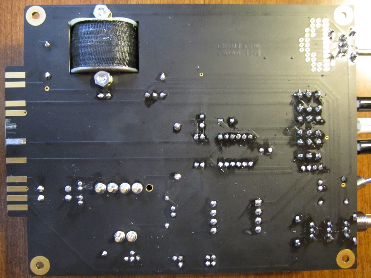
Attached are some pictures of the bottom of the board.  I checked continuity between all the closest solder points to see if they were shorting and none  were.

Again, I really appreciate the help.

Michael

IMG_1153.JPG


Nothing really jumping out on the bottom either except what looks to be solder on the gold finger #8. I don't think that would be an issue though.

The reading between C and O is most likely DMM related. Either battery, range or auto-range related. As long as it's not a dead short, you should be fine.

While the rack is open, with no module installed, power off, you might as well verify the rear XLR connections to the card edge connector. I would beep them out or measure resistance. For the input, XLR pin 2 should go to card edge pin #10 and XLR pin 3 should go to card edge pin #8. For the output, XLR pin 2 should go to card edge pin #2 and XLR pin 3 should go to card edge pin #4.

Next up would be injecting some signal at the input and tracing with a scope probe or DMM set to ACV. You will need to follow the signal along the schematic probing at each side of each component to see where it stops. As a tip, a balanced H-pad is a great thing for this. Using this calculator, you will want an input Z of 10,000 ohms, output Z of 150 ohms with a pad loss of around 36dB. You can then use a sig generator from a sound card or whatever to inject around a -43dB signal, with the gain knob around 2:00, should give you an output of around +4dB. Make sure you match the like R's to as close as your DMM with measure. .1% precision R's are great for this but hard to find without spending an arm and leg.

Be careful when probing around not to wedge a probe tip between a component lead and the top of the PCB. This could possibly cause a short to the ground plane which is on top of the PCB.
 
Checked the continuity between xlr inputs and they are fine.  I've never done any signal generation testing, and my schematic skills are missing, so I'll be reading up on that stuff and hopefully will be able to check the rest soon.  Thanks again!

 
Bro, what is up with one of the gold fingers on the card?  it looks like it doesn't have any gold at all on it.  Also, are you sure you used a *working* op amp when you fired it up?
 
mulletchuck said:
Bro, what is up with one of the gold fingers on the card?  it looks like it doesn't have any gold at all on it.  Also, are you sure you used a *working* op amp when you fired it up?
Chuck, I think some solder was dropped on that gold finger. The opamp is one of Scott's red dots so that should be OK.
 

Latest posts

Back
Top