[BUILD] fripholm's TG1 Zener Limiter boards - support thread

GroupDIY Audio Forum

Help Support GroupDIY Audio Forum:

This site may earn a commission from merchant affiliate links, including eBay, Amazon, and others.
You may try a couple more things. Inject test signal directly into output pot. This will confirm if the issue is in the output stage or not.
If it's the output stage, build this circuit in a simulator and check against the real one. This may give you some clues on what is wrong with your build.
 
I pulled R30 and C8 and wired in a test lead to where it connects those components to the CW connection of the output pot. I found that I start picking up noise where T1 connects to D2 and where T2 connects to D4. I have to short the base and emitter of both of T1 and T2 to get enough signal to make a comparison, which is clean. The signal on both sides of D5 is also clean. I had already pulled D1-D4 out and did the bypass with the 120k and I still had noise. Is it possible that both T1 and T2 are bad? Keep in mind that this is the third board I've built with different parts from different manufacturers and I've had this noise problem on all of them, with the first attempt having higher noise than the others. Not saying it's impossible that they are all bad, but it's highly unlikely. My other thought is to reinstall R30 and C8 and remove T3 and T4 and see I get a cleaner signal when injecting tone after those parts, but before I do a bunch more unsoldering, I'm hoping someone here can offer some better suggestions that would prevent me from needlessly hacking away on this board.

I now know for certain that the output section is functioning properly. I also believe the wiring is not the culprit as well. This time.

Thanks!

Paul
 
Paul, this one struck my mind the other day: Have you ever tried this without an input transformer, going directly into the input pin unbalanced? Does that help with the noise?

Maybe your input transformer is ringing heavily at HF and you need a zobel network across the secondary. Look up the datasheet of the transformer and/or experiment with different values.
 
I have been thinking about this too, but if it's clean in bypass, wouldn't that mean the transformer is not at fault? Or am I incorrect thinking about it this way? If it's because I need a zobel network, then that would be great news indeed!

And thanks for all your help on this project. I know the dangers of offering a PCB to the public, and I appreciate you taking the time for your assistance.

Thanks!

Paul
 
Potato Cakes said:
I have been thinking about this too, but if it's clean in bypass, wouldn't that mean the transformer is not at fault? Or am I incorrect thinking about it this way? If it's because I need a zobel network, then that would be great news indeed!

And thanks for all your help on this project. I know the dangers of offering a PCB to the public, and I appreciate you taking the time for your assistance.

You're welcome!

Maybe there's some HF interaction with the compressor and/or sidechain stage at work here that's way over our heads  :D

I would try it anyway - it's just a resistor and a small cap. You could also temporarily connect just a cap (start with a film cap, 100n~1uF) across the secondary. Depending on your input transformer, this filters out high frequencies completely and could give you a hint whether you're on the right track...
 
It appears that a Zobel network is not the answer. The noise is still present when the input transformer is disconnected.

I did some more testing. I pulled T1-T4 and soldered C8 and R30 back in place. I picked the signal at R93 after the input gain pot and started injecting tone downstream and found that at the anode of D2 and 4 no noise added but there was at the anode of D1 and 3. This carried downstream and then the noise went away where R30 and C8 connect and go to the output pot. So I guess my next course of action would be to pull D1 and D3 and check again. I'll do that a little bit later as I need a break from pulling the board out of the case and desoldering parts. If it does turn out to be the diodes I will find that to be very hilarious.

Thanks!

Paul
 
So after pulling D1 and D3, I find that I still get noise when I touch the test probe on the cathode side of the respective diode connections and it continues like before and stops at R30. The noise occurs even when there is no tone being generated and goes away when the probe is removed. So I put D1 and D3 as well as T1-4 and made an unbalanced cable to go directly to BYP1 and used a jumper to make the appropriate connection to BYP2 to take the relay out and the input transformer out of the chain but I still get the same noise results. The attached picture shows the noise when idle and with tone the 1kHz peak is at -20dBFS.

I'm at a loss here. I've have some really sneaky problems that I've been able to solve in the past, but I've done everything I know to do and have maxed my abilities to understand and strategize a troubleshooting approach. If I could find out why I am getting noise when I touch the end of the probe to D1 or D3 or even when they are removed from the circuit then may I could find the culprit. I noticed that where I am injecting signal is also attached to the +20V rail, so maybe that is disrupting something.

Whatever it is, I think I've exhausted all the possibilities that I have been able to take into consideration. Somewhere after the input pot, not in the sidechain section, not the zeners and not in the output section is the answer to this mystery. The one thing that I thought might help is if the ground plane was separated from the audio ground, but if no one else is having problems like this then I don't know if it would be beneficial. I did manage to blow up D12, T15, and/or Q14 on one of the boards while I was trying to find were the noise was originating, so now that channel's output doesn't work. I'm probably going to put this one off to the side for now. Maybe later I will build one of these in reverse order of the schematic signal flow and see when I can start to make noise happen.

Thanks!

Paul
 

Attachments

  • Noise.jpg
    Noise.jpg
    179.7 KB
I also noticed that on the original schematic that VT13 and VT14 (T7 and 8 respectively) are supposed to be a matched pair. Would this make any sort of difference on the current schematic?

Thanks!

Paul
 
Potato Cakes said:
I did some more testing. I pulled T1-T4 and soldered C8 and R30 back in place. I picked the signal at R93 after the input gain pot and started injecting tone downstream and found that at the anode of D2 and 4 no noise added but there was at the anode of D1 and 3. This carried downstream and then the noise went away where R30 and C8 connect and go to the output pot.

As I understand the circuit description of the original, only the leg with T2, D3 and D4 is directly fed with signal and is a first amplifier stage. The other leg consisting of T1, D1 and D2 is biased the same way for temperature compensation but is not fed with signal, so I think it's normal you won't get any noise added there. It's a mystery to me, that the noise disappears at the junction of R30/C8 - because that IS the output of the compressor stage which is fed to the output stage where you can clearly hear it again. Doesn't make any sense...

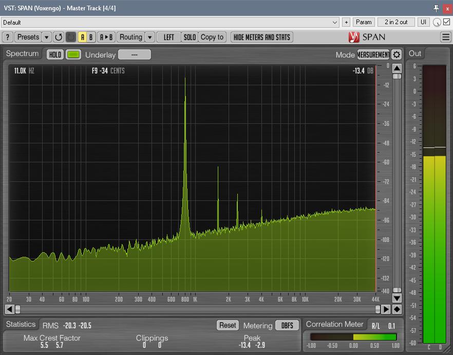
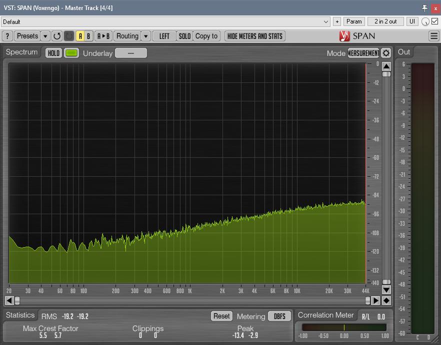
From looking at your frequency plot, I would say it's pretty normal. But can't say for sure as it's not obvious to what reference level your interface is set to and what the compressor's controls are set to. Digicheck's noise measurement for my Fireface UFX+ (0dBu is set to -13dBFS on both inputs and outputs) tells me, the noise of my stereo unit is at -87 dBFS (RMS a-weighted), which calculates to about -74 dBu. Your plot is between -80 and -90, which falls in line with those numbers - if the noise were not a radio station playing country music...  8)

To measure this, I inject a 0dBu signal (-13dBFS) to the input, adjust the input control until the compressor just slightly starts compressing and adjust the output control to get the same signal level back into the interface again (-13dBFS). If your interface is set to -14 or -18 or whatever, you take these numbers. This way you get consistent readings. Noise measurement is taken without input signal of course.

What happens, if you close the lid or you cover the board with a huge steel cooking pot or something similar? Does that keep the radio station out?


The noise doesn't seem to go away with the lid closed as I thought the same thing. The station only comes in clear when I hold the cable to the BYP2 connection, which is made less of a problem since I switched to shielded cable for this connection. The noise that you see on in the photo is all static but I do seem to hear way background a radio signal. At least I'm almost really sure.

I'll do your test with setting the compressor and see how that impacts the noise level. For over all output when adjusting the distortion, my meters in logic would read about -7dbFS and with no signal the noise would read about -65dB. I will have to double check but I remember it being close to that. None of the other builds I've completed have had this much noise unless something was wrong, so that has prompted me to really tear into this guy and try find out why this one has a higher noise floor.

I am a little baffled as well at the R30/C8 being cleaner than the points proceeding it. I also think I might have spent so much time repeating the process of removing the PCB from the case, soldering/desoldering, then testing again, I start to loose track of where I am. I might need to set this to the side for a while as I am starting to make things worse working on this guy. I think one thing I might is separating the audio ground from the top ground plane and have two connections going to the star ground from the PCB.

Maybe if you get an chance you could post a screen shot of your analyzer with and without signal to see what kind of noise readings you are getting.

Thanks!

Paul

 
I'm usually using Voxengo's GlissEQ as my analyzer, but their SPAN has the same flexible and very detailed frequency plot and it's free. I'd strongly encourage you to download and install it. It's very important to use the same analyzer settings, so we can compare apples to apples. Here's the spectrum preset I'm using (called "Measurement"). Unzip this file to your Voxengo user folder after installing. On Windows it's at C:\Users\YOUR USERNAME\AppData\Roaming\Voxengo\ - don't kow where it goes on Mac. Make sure to reload the plugin after copying the file...

This is the plot with signal @ -13dBFS:
withsig.jpg


No signal, only left channel shown:
nosig.jpg


I just realised, that I've made a mistake in my earlier post. The real noise numbers from Digicheck should be -80.4 dBFS (RMS A-weighted) which is about -67dBu.
 
Hi Paul,

I built a 2nd stereo unit recently that had a similar issue to yours. The right side was quite noisy only when engaged, in bypass mode it was silent.

I took the board out, touched up solder joints and any potential micro bridges, etc. I also swapped out the 4 751 zeners too and the noise floor issue was dramatically lowered. I'm not sure exactly what did the trick but figured I would mention what worked for me...
 
Just getting back to this.

I did the prescribed steps for setting up the input/output gains and have attached a pic of what it looks like in SPAN. The preset you attached wasn't recognized, but I was able to copy settings from the screen shot you provided.

The channel used is the noisier of the two by about 5-6dB. I have confirmed noise level difference is related to the board and not the proximity to the PSU or power transformer. I put all the connections back to how they are prescribed in the build manual after doing dozens of tests and soldering/resoldering parts many times with no change to the noise level.

I have changed the 751A's out several times as well as using shielded cable and bypassing the input transformer. So as far as I can tell, the unit is working properly, just seems to have more noise than what would be expected using modern components. I'd like to put this to rest this week before I leave on tour, because when I get back, I plan on finally organizing everything in a proper studio setup and get back to making music. I'm planning on using this in the setup, but I would rather not have to factor in the noise level every time I use it.

Thanks!

Paul
 

Attachments

  • Noise Voxengo.jpg
    Noise Voxengo.jpg
    574.9 KB
My next line of thinking is if there are other models of zeners that can be used that would give equivalent or even better results both in noise and subjective audio qualities? I don't need this to sound exactly like the TG Limiter on which this circuit is based. If there have been reports of the 751A causing noise in this and other similar PCB designs, then maybe finding a suitable alternative(s) would alleviate this "problem" all together.

On a quick glance, it seems that the 1N5231 seems to be a likely candidate for this application and is RoHS for those that care or need to care about this. The DIY-Racked version of this circuit even lists it as an alternative in the BOM.

Thanks!

Paul
 
Potato Cakes said:
My next line of thinking is if there are other models of zeners that can be used that would give equivalent or even better results both in noise and subjective audio qualities?

...snip....

On a quick glance, it seems that the 1N5231 seems to be a likely candidate for this application and is RoHS for those that care or need to care about this. The DIY-Racked version of this circuit even lists it as an alternative in the BOM.
Are your zeners from the same batch or from different? If from the same, it's highly unlikely that they are the culprit (since you have one channel working fine).

I'd swap zeners between the channels and see if the noise issue moves with them. Don't remember if you've done this already or not. The circuit should NOT rectify radio, but with noisy zeners you can have drastically higher noise floor, but no radio.

1N5231 may be actually even better than 1N751. At least according to my notes. Definitely try them out. ROHS has nothing to do with zeners suitability. But different manufacturers can have different processes, so get the same model from different manufacturers if you can.
 
I have swapped zeners several times from different manufacturers. And even though the channel not being tested is quieter, it's only a little less. The mention of RoHS was only referring to accessibility in places where "the State knows best" and not in terms of performance.

I might order some this week and see if they make a difference.

Thanks!

Paul
 
I ordered some 1N5231 and wi ll report when I get them installed.

One thing I thought about is somehow shifting the inherent gain characteristics for the input and output to lower the noise floor. So if a different input transformer ratio is used to increase the signal level going into the unit, then changing the values for where the threshold of the compressor is higher (different value for the threshold control and or fixed resistor in line with the pot) to where the same or similar gain reduction is taking place at similar positions of the potentiometer in relation to CW/CCW and then reducing the level before it hits the output control to get the level leaving the unit to be the same as before, then we should get a much better S/N ratio. I don't know much of the history of the original circuit, but if it is true the sound is in the zeners, then how we do the gain structure around them shouldn't matter too much.

I could rewire my Sowter input transformers to be 1:3 then pad the signal before it hits the circuit to the desired amount. Then I would have to play with the compression circuit sensitivity and figure out where to alter the signal level before the gain pot. I would probably need someone a bit smarter to guide and give suggestions where to accomplish all of this. I'll stare at the schematic a bit more and see if I can figure out where to start.

Thanks!

Paul
 
At a quick glance and with my child like understanding of electron behavior, It seems that increasing the values for R25 and R27 would decrease the signal feeding the side chain circuit and hopefully require more input signal to work. The place to do this would seem to be R73 and R74. For the decreasing the signal to the output pot it would seem that decreasing the value of R30 would accomplish this. I honestly don't know if there would be any adverse affects to circuit outside of my intended goals.

Thanks!

Paul
 
If you increase the input level, you get higher level across the zeners. This will get you higher THD. You can increase the level only so much before you get distortion of unacceptable levels.
 
Back
Top