You are using an out of date browser. It may not display this or other websites correctly.
You should upgrade or use an alternative browser.
You should upgrade or use an alternative browser.
[BUILD] fripholm's TG1 Zener Limiter boards - support thread
- Thread starter fripholm
- Start date


Help Support GroupDIY Audio Forum:
This site may earn a commission from merchant affiliate
links, including eBay, Amazon, and others.

BerndVP said:So, didn't found it or I looked over it, but how do I need to wire the Input transfo to get 2:1 ?
I'm using the VTB9046
Wire both sides in series OR both in parallel. Fripholm recommended series to me previously for better low end response, I believe.
The impedance ratio is the square of the turns ratio, so 10k:2.4k ohms when wired in series (approximately 4:1) is equal to 2:1 squared. Same goes for parallel, 2.4k:600.
You can see in the data sheet that either of these options gets you the -6dB drop that we are looking for going into the circuit.
I don't know if I understand your question correctly.
Auto release introduces two different timing constants to the sidechain signal - simply put a short and a longer one that are dependent on the input signal's dynamic. The way the auto release is implemented on my boards is that you still have control over the short part, the long one is fixed.
If you mean by 'longest position' the longest time constant - aka release pot fully clockwise - then you would have no control anymore and both parts were fixed (and the short one much too slow most of the time).
If that's not what you meant, please clarify")
Auto release introduces two different timing constants to the sidechain signal - simply put a short and a longer one that are dependent on the input signal's dynamic. The way the auto release is implemented on my boards is that you still have control over the short part, the long one is fixed.
If you mean by 'longest position' the longest time constant - aka release pot fully clockwise - then you would have no control anymore and both parts were fixed (and the short one much too slow most of the time).
If that's not what you meant, please clarify
Hi, sorry, I'm asking it wrong.
My Auto Release Pot is an pot and a DPDT switch in one.
You can push the pot to change de DPDT Switch.
You have:
Position 1: shorter shaft
Position 2: longer shaft
I attached an picture of the AutoRelease on you're board with two wires as if the switch was connected.
So in what position do you enable AutoRelease
Attachments


ok, then I wired it correctly like I want.
Then for Input / Output gain I'm going for ELMA 04 and the resistors from you list in the manual.
I'm using this little PCB to make it easier to build.
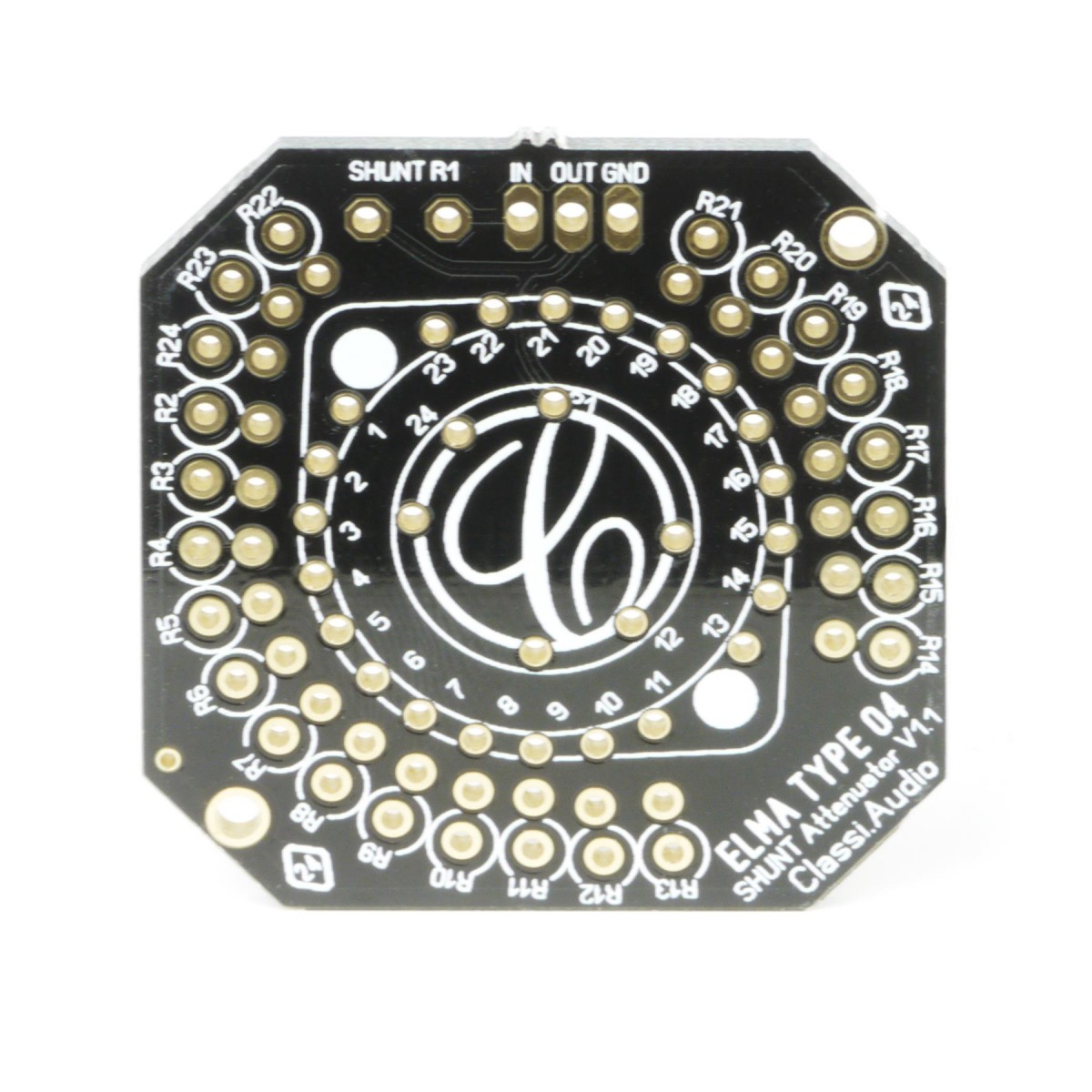
So In position 1 there is no resistor from the list active ? or how do I need to see this ?
I attached an screenshot from another project so, I hope you understand what I'm asking.
Then for Input / Output gain I'm going for ELMA 04 and the resistors from you list in the manual.
I'm using this little PCB to make it easier to build.
So In position 1 there is no resistor from the list active ? or how do I need to see this ?
I attached an screenshot from another project so, I hope you understand what I'm asking.
Attachments

Position 1 on your screenshot looks like no attenuation/full signal at the 'wiper' of the switch. The lowest position on the other hand has a resistor on the board in series to ground which means the 'wiper' is not fully muted.
So,
as told before I'm using the Elma Type 04 for input and Output. I used you're resistor list
and the PCB from Don Audio.
I soldered the input that 'R1 = 30, R2 = 36,..., R23 = 1K6' so this leaves Position 24 open.
output: 'R1 = 270, R2 = 330,..., R23 = 120' and this leaves position 24 open.
I hope this is correct ?
If I then use a DDM and measure I got:
Input: Pos 1 0R, Pos 2: 30R, Pos 24: +-10K
Output: Pos 1 0R, Pos 2: 270R, Pos 24: +-10K
If this is correct, how do I need to wire this to the PCB ?
For the input I guess the wiper goes to the C1 cap ?
But what for the other two cables ?
For the output I guess the wiper goes to the C34 cap ?
But what for the other two cables ?
You're right about each of the wipers.
When the switch is in its fully counter-clockwise position (lowest signal level) then the wires with the zero Ohms resistance with respect to the wiper go to either R93 (input) or R94 (output).
When you look at the silkscreen reference image on page 13 of the guide then it's the upper pad of the INPUTGAIN connector and the lower pad of OUTPUTGAIN. The next higher step on the switch should read either 30R (input) or 270R (output). HTH
OK, got it.
Now I think this is one of the last assembly questions.
Where do I need to connect the input transfo to ?
The output one is easy, but input one is not completely clear to me.
I'm going to use a relay to do the BYPASS switching.
Now I think this is one of the last assembly questions.
Where do I need to connect the input transfo to ?
The output one is easy, but input one is not completely clear to me.
I'm going to use a relay to do the BYPASS switching.
BerndVP said:Where do I need to connect the input transfo to ?
There's a diagram on how to connect the input transformer to a relay on page 2 of the build guide.
fripholm said:It's a ground connection as discussed here.
I was unsure about this also.
I looked at the post you linked, and if I’m understanding correctly, the ”—“ leads of both the input xfmr secondary AND the output xfmr primary connect to the same place, the output ground pad on the pcb?
Additionally, the build guide specifies that the “+” lead from the input xfmr that connects to the relay should be shielded. Where should that shield be connected?
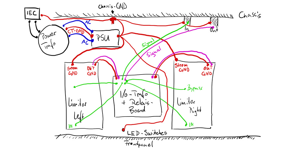
When I designed this, I always had both the input and output transformers on a single perfboard (third picture from the top in this post). In this case it was convenient enough to just use the GND pad from the output section as the only ground connection to the rest of the circuit. In my units there was no need for a shielded wire to the relay because of the close proximity to the transformer on the same perfboard. So, that 'specification' is merely a recommendation for longer leads and might not be necessary at all. However, the I/O wires from the perfboard to the XLR connectors are shielded and the shields connect directly to Pin 1.
The following quick sketch shows how my stereo unit is wired (red lines are GND, differential signal connections are shown as single line):
I understand that one might not be able to mount all types of transformers on perfboard. I've already planned a ground pad near the input connector for a possible future board revision but this may take some time.
For the time being you could use a solid copper wire with the isolation stripped as some kind of 'bus bar' which connects to all I/O transformer grounds and terminates at the GND pad of the output connector (or any GND pad near the input section).
Okay, I get it now. Thanks!
Any reason that signal ground from STROM needs to connect to the PSU ground? Could they both go directly to chassis ground without intersecting prior to that point?
Any reason that signal ground from STROM needs to connect to the PSU ground? Could they both go directly to chassis ground without intersecting prior to that point?
JMan said:Any reason that signal ground from STROM needs to connect to the PSU ground?
As far as I understand, current wants to return the same (and shortest possible) way it came, so it seemed logical to return the power supply rails through the GND wire to the PSU board first and then tie it all together at chassis ground.
I may have to add that the I/O perfboard has separate ground paths for the left and the right channel. Otherwise there would be a ground loop.
fripholm said:As far as I understand, current wants to return the same (and shortest possible) way it came, so it seemed logical to return the power supply rails through the GND wire to the PSU board first and then tie it all together at chassis ground.
I may have to add that the I/O perfboard has separate ground paths for the left and the right channel. Otherwise there would be a ground loop.
Ah, okay!
Similar threads
- Replies
- 43
- Views
- 12K
- Replies
- 183
- Views
- 52K