[BUILD] fripholm's TG1 Zener Limiter boards - support thread

GroupDIY Audio Forum

Help Support GroupDIY Audio Forum:

This site may earn a commission from merchant affiliate links, including eBay, Amazon, and others.
Oh, one more question.  If implementing the Hold function, the middle pad and ground/square pad of the Auto-release section must be jumped, right?  (The guide says to do this "if not using auto release").  Or should all three of the auto-release pads remain unconnected if implementing Hold?

I posted several months ago my plan to make my unit switchable between auto-release and hold (either/or/neither), and upon revisiting that plan I realized that I need to adjust one connection on my switch, but the answer to the question above will determine exactly how I do it.

Sorry to bombard the thread with questions today!

EDIT: Upon yet another pass through the manual, I think that these pads are meant to be fully disconnected when implementing Hold. 
 
JMan said:
FT1 - all that is needed here is the 10k trimmer, right?  By my math, it looks like I should pre-trim it for approximately 4k ohms and adjust on test.  No fixed resistors for R7/8 in this case.
Correct. Pre-trimming shouldn't be necessary. You won't break anything at either end of the range and in my experience, most new trimmers are pre-set to the middle of their range anyways.

FT2A - You either place a 12k resistor in R22 and jump the middle and square pads of FT2A, OR you install a 10k resistor for R22 and a 20k trimmer for FT2A for adjustment. 
Correct.

FT2B - A 2k trimmer (FT2B) is installed instead of R56.

My question on FT2A is, if the rough target resistance for R22 (or the total resistance between T5 and R25, as it were) is 12k, why does the second option use a 10k resistor and a 20k trimmer in series?  Wouldn't a 5k trimmer make more sense?  Or am I missing something here, because I'm feeling like I'm missing something...  I see that you mention in the guide that your right channel's final value for R22 was around 18k, so I guess the larger trimmer value is to compensate for wide swings like that?
Also correct but if I were you I would leave it alone and just go with the 12k unless I couldn't get it to work otherwise.

And one final unrelated question: For C13, what are the pros/cons of using a tantalum instead of a regular electrolytic?  I have used tants in other builds when called for, but I always hear such conflicting information about whether they are good or bad.  Given the option here, I don't know what to choose or why.
Doesn't really matter. Use whatever you have. I have used tants, electrolytics and film caps in various types of compressors and all of them filter the control voltage just fine. No fairy dust involved ;)

Or should all three of the auto-release pads remain unconnected if implementing Hold?
Yes. The most important thing is that R51 is not directly connected to ground when HOLD is implemented.

OTOH, you shouldn't really need an option to turn HOLD off as it's basically off when the hold pot is turned fully counter-clockwise (ie. the wiper is at GND).
I've just tried to implement auto-release (as it is on the board) AND hold at the same time in LTSpice. As it turns out it doesn't break anything. Hold still works as expected with it in the circuit but I don't know if the auto-release timings stay the same. You have to try it yourself.

Ideally, the grounded ends of C32 and R90 would need to terminate at the hold pot's wiper as well...
 
fripholm said:
Yes. The most important thing is that R51 is not directly connected to ground when HOLD is implemented.

OTOH, you shouldn't really need an option to turn HOLD off as it's basically off when the hold pot is turned fully counter-clockwise (ie. the wiper is at GND).
I've just tried to implement auto-release (as it is on the board) AND hold at the same time in LTSpice. As it turns out it doesn't break anything. Hold still works as expected with it in the circuit but I don't know if the auto-release timings stay the same. You have to try it yourself.

Ideally, the grounded ends of C32 and R90 would need to terminate at the hold pot's wiper as well...

Thanks for all of the answers!

Okay, that makes sense.  The way that I am implementing Auto-release and Hold is on two separate, interdependent toggle switches (a DPDT and a 4PDT).  Auto-release will be on the DPDT switch, just like it is meant to be.  When I toggle the 4PDT Hold switch "on," the connections for Auto-release will be broken (R51 will not connect directly to ground OR to C32/R90, but rather to the Hold pot wiper and the anode of the added 1N4153 diode) and the connections for Hold will be made, and the auto-release switch will no longer function.  In this way, I am making it so that I can use either Hold or Auto-release, mutually exclusive to one another, at any given time, OR opt to have neither one engaged.  Don't know if this description was clear, but I'll share my wiring diagram at some point when I have a chance.

The main reason I'm doing it this way it two-fold, and somewhat silly perhaps -- first, since the build guide presented Hold and AR as either/or options, I got it in my head to think of them as such, and that notion just kind of stuck; second, totally for vanity's sake, the proportions of my front panel design look a little better with a couple toggle switches breaking up some of the empty space!  ;D  Your answer was very helpful in confirming how I've planned this wiring, thank you!
 
So, I often have these half-cocked late-night thoughts that don't bear much merit. I'm gonna lead with that, because I feel like what I'm going to ask is only going to have one reasonable answer: "No, dummy, obviously not."

The output section of this circuit inverts the phase of the signal, right? And we flip it back with a simple swap of the pins on the XLR. Is there any good use for a phase flip switch on a compressor? I mean...it would be so easy to do, and I'm a glutton for adding [unnecessary] switches and such. I honestly can't quite imagine it doing anything useful -- probably quite the opposite -- but darn it, this is what keeps me up at night! o_O (Truly, though, exploring ideas like this is a big part of the learning process for me, even when the idea itself is a dead end).
 
Personally, I don't know of any standalone compressor device that has a polarity switch. I think this is mostly due to the fact that they're traditionally used after tracking is done and any polarity issues have already been solved. It makes sense for channel strips that include a compressor next to e.g. a mic pre and/or EQ.

OTOH, if you have the space for another switch and it doesn't clutter up the front panel - go for it, it's yours... :)
 
OTOH, if you have the space for another switch and it doesn't clutter up the front panel - go for it, it's yours... :)
Haha you were supposed to talk me out of it! :ROFLMAO: But seriously, that makes sense. I can't quite imagine it being terribly useful -- I wonder what kind of havoc it could wreak when using this unit for parallel compression (and not in a euphemistic "cool" sort of way). Feels like that could get really awful.

Having said that, just for the heck of it, I might put it on the back panel as a hidden vanity function that will never get used, but I can say that it's there. Bells and whistles, you know...
 
Question on the input transformer.

I've got the Carnhill VTB9046M (the one with the mu metal can). It has two additional pins -- 6 (earth) and 11 (mu metal case). What, if anything, do I need to do with these?

The transformer itself will be affixed to the enclosure, so I'm guessing that pin 11 is superfluous in this situation. I'm less sure about what pin 6 is doing, though.
 

Attachments

  • Screen Shot 2020-10-06 at 9.58.57 PM.png
    Screen Shot 2020-10-06 at 9.58.57 PM.png
    36.7 KB
I might be the world's slowest worker, but I have FINALLY started to actually work on the wiring. (Not pictured: my hand-drilled proto-frontpanel, which is considerably busier).

Also, anyone know about that pin 6 ("earth") on the Carnhill transformer that I asked about above? Do I need to mess with it, or leave it alone?
 

Attachments

  • IMG_1862.jpg
    IMG_1862.jpg
    211.6 KB
Make sure that Pin 11 has a good electrical connection to the chassis (ideally your star ground) and connect Pin 6 to it as well. I'm by no means a transformer expert but I believe grounding this shield helps to reduce capacitive crosstalk between windings. Somebody please correct me if I'm wrong.
 
I'd rather connect the internal core to the clean audio ground, not to the chassis. Dirty ground may cause coupling of unwanted noise to the windings, and you don't want that.
 
I'd rather connect the internal core to the clean audio ground, not to the chassis. Dirty ground may cause coupling of unwanted noise to the windings, and you don't want that.
Interesting point! Okay, so I see two other options (aside from chassis) where I could connect that internal core. I could either connect it to the same signal ground pad on the main board that the grounded end of the secondary side of the input transformer connects to; or I could connect it to the ground pad on the PSU where the various other grounds -- signal ground plus some off-board relays and LEDS -- all converge before connecting to the chassis. Does one of these make more sense than the other?
 
When in doubt, I usually have the questionable ground connection on a wire and try different options before committing to the one with the lowest noise. Trial and error...
 
Last edited:
Fair enough! I'm one of those people who tends to overthink things in an effort to get it right on the first pass (as evidenced by my many questions on this thread! 😬 ), but it won't kill me to experiment with this one.
 
@fripholm:
In the PDF guide you are writing that you compared your output stage to the original. Did you compare the maximum gain of both?
While I'm still super happy with mine, a little more gain from the output stage would be nice...
 
The gain in the output stage is about the same - even slightly higher compared to the original (0.5dB).
 
Hey I got my PCBs (thanks fripholm). I have some other projects to finish first. So it will take a while before I start.

I’m also still learning a lot. I’ve been looking at the schematic and it seems a bit more complicated than other compressor circuits.. Do you guys know where I can find out a bit more of the functionality of this circuit. What is the role of the zeners for example.. What happens where in the circuit. Would love a rundown

Would be good to study it a bit more before building. Also makes trouble shooting way easier..

Any help/tips appreciated.
 
Is there an easy way to get a little more gain from the output stage on your PCB?

First of all: are you sure, your unit is set up/calibrated correctly? Increasing the gain shouldn't be necessary - the output stage already has ~24 dB of gain. As I mentioned in an earlier post, unity gain on my stereo unit is with both input and output knobs at 11 o'clock which leaves plenty of additional gain on the output.

Would be good to study it a bit more before building. Also makes trouble shooting way easier..

Any help/tips appreciated.

Google for

TG12413_DESCR.pdf

exactly as written above. This should get you to a PDF file that describes the original circuit using original component designations (mine are different). You could also search for the original schematic in GDIY's Tec Docs sub forum. Helps to follow along with the description...
 
Still have to finish this unit, I put the project aside because of other things, but what I can remember is that I had noise on the input and output of the unit, even with very low input, putting in THD mode totally distorted the signal path.

I followed the wiring that was mention over here, with STAR Ground and stuff.

So have to look again at the unit for this.

Maybe it's more an issue with too small power cabling to the boards ? or maybe a to big power transfo, it's an 160VA that I use, I had nothing smaller.
 
It's a nice build indeed. Regarding the front panel, I wouldn't change a thing - looks great :)


Here's a quick tip to reduce hum induced by internal power transformers:

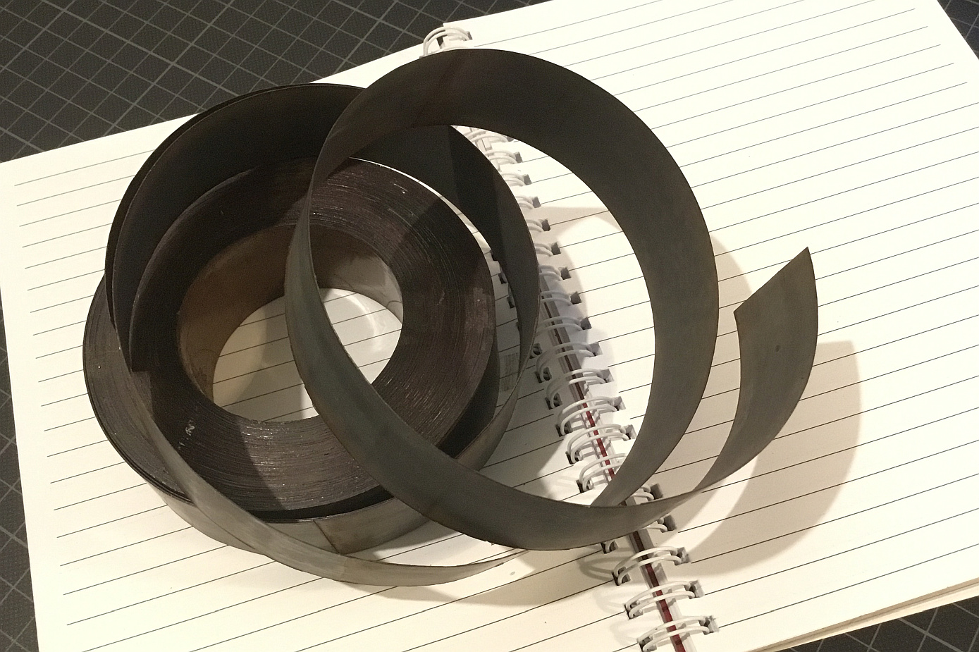
lams.jpg


These are the lams of a 300W power transformer from an old halogen string light that I 'reverse-engineered' a few years ago. The lams are similar to the transformer shields you can buy at e.g. Don Audio. Those work fine but are insanely overpriced IMHO.

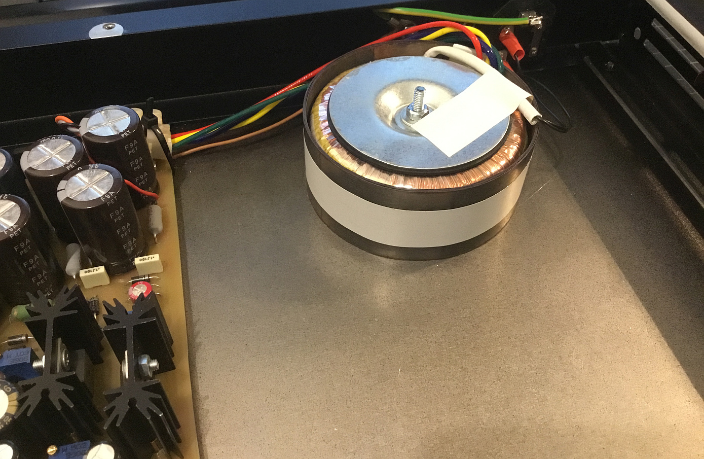
I just wrap two or three layers of these lams around my internal power transformer and secure it with electrical tape. Both of my TG units have it as well. Here it is in a 6-channel mic pre that I designed:

wrapped.jpg


Place the transformer as far as possible from audio circuitry, wrap the lams around it and rotate till the hum is gone. HTH
Door noob question (again..). I’m trying to find these lams. but no luck so far. What kind of transformer was this? As in what type..
 
Back
Top