Echo North
Well-known member
Deejsirois said:Yes, that is correct.
Definitely something in your GR Meter Driver Amp section. You've been through that a few times?
Mike


Deejsirois said:Yes, that is correct.
Hairball Audio said:Those caps are right.
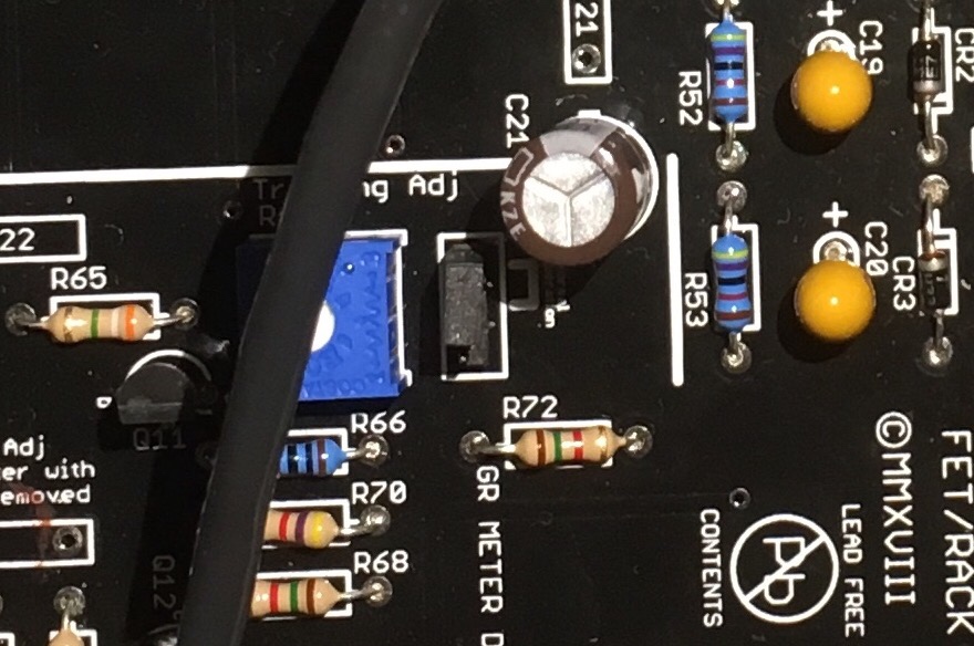
Some of those components have no solder flow on the top, that's not necessarily a problem, but it might mean you have a part that's not fully soldered. You might want to reflow these joints, particularly those in the signal amp.
Mike
Hairball Audio said:Working now?
A needle worth of swing on the release pot is normal.
Mike
Hairball Audio said:You have something going on in the GR Control amp. Check your DC voltages for each transistor in that section...use the D chart linked in the troubleshoot guide.
")
Anode said:Hi all
Anyone have a procedure for REV F Tracking adjust because there isn't PIN SHUNT on the PCB.
Thanks by advance.
Best
Anode
ron_swanson said:Hey Mike,
I basically pulled apart the GR Control Amp section - tested all resistors, caps, transistors, diodes and then reassembled / re-soldered. Nothing seemed out of place and everything tested positive as expected. The good news, it's working now and I've been able to calibrate! Won't be in the studio for a few days, so it will be awhile before I can test in a 'real use' environment, but all seems well now at least on the bench using a low end I/O and micro desk speakers. The bad news - unfortunately - is... I don't know what exactly the problem was? Since all components tested correctly stuffed correctly, a bad solder point or other?
Lastly, it would be nice if the calibration and troubleshooting pages could be updated with specific F unit instructions when someone gets a chance.
Anyway, thanks for the assistance. Time to get rocking!
Cheers, Greg
Joarsylvan said:Hello again! I went over the soldering and found a couple of not great ones. Those are now fixed.
I now have a clean signal, no distortion. But it’s still quite low and it looses its strength somewhere early in the chain. And no compression, just clean (but low) signal.
Cables are testes, everything seems to be in it’s right place and every resistor is tested three times at the least.
Since I don’t have a clue now concerning what could be wrong I’m thinking that I am left with no alternative but to send the pcb to you. Maybe one of the caps or transformators are broken? Idk.
Oh, and I think I broke the R71 adjustment when trying to calibrate the VU meter... :
kingofspain2 said:all Qs are within volt tolerances of 10%, q2 base however is reading 0.86 volts instead of 1.06 volts, there's also a hyper sensitivity to the amplitude of the noise when touching R8 or C1, signal ground and chassis are separate, entire chassis is continuous... thoughts?
kingofspain2 said:all Qs are within volt tolerances of 10%, q2 base however is reading 0.86 volts instead of 1.06 volts, there's also a hyper sensitivity to the amplitude of the noise when touching R8 or C1, signal ground and chassis are separate, entire chassis is continuous... thoughts?
scott2000 said:signal ground and chassis not connected???
Nowhere?
kingofspain2 said:chasis is connected to ground at cathode of c25
Hairball Audio said:It's hard to say. Could be a lot of things.Have you checked the transistor DC voltages?
kingofspain2 said:A working rack unit had the main board swapped with the noisy unit to isolate where the noise is originating, the issue remained in the rack chassis that is noisy, the noisy board works fine in the working chassis, the noise in the working unit is persistent before and after the swap, but it's within the noise floor and isn't an issue.
further investigation in the chassis components finds that the noise disappears when any of the lugs on the attack pot are probed with an oscilloscope, and that removing the violet wire from the ratio board connector to the main board stops the noise. Also from a cold condition, the noise seems to only appear when the +20 ratio button is pressed on it's own or with any other button combination with +20 pressed. Grounding the attack pot lugs also gets rid of the noise completly, not the switch lugs, just the potentiometer lugs, as well as the release pot lugs. Current suspects are the ratio button board, attack pot, and release pot, however none of these parts appear to have anything wrong with them, any advice is appreciated.
frenkonio said:Hi guys, got an issue on a Rev. A I successfully built one year ago. From today everything passes inside the compressor gets out with something like an HPF on everytime.
Any idea on where to start troubleshooting?
kingofspain2 said:Picture of rack, board is fine, was swapped with working unit, problem didn't migrate with board, has to be chassis issue
Nope, I got no low end frequencies, looks like an hpf filter on.Hairball Audio said:You've got no high end?
Do the signal test through the unit as described in the troubleshooting guide using a 500 Hz signal (note TP1, TP15, Output BRN). Then do it again with a 10KHz and see where you are dumping the signal.
Mike


![Soldering Iron Kit, 120W LED Digital Advanced Solder Iron Soldering Gun kit, 110V Welding Tools, Smart Temperature Control [356℉-932℉], Extra 5pcs Tips, Auto Sleep, Temp Calibration, Orange](https://m.media-amazon.com/images/I/51sFKu9SdeL._SL500_.jpg)


