Vac11
Well-known member
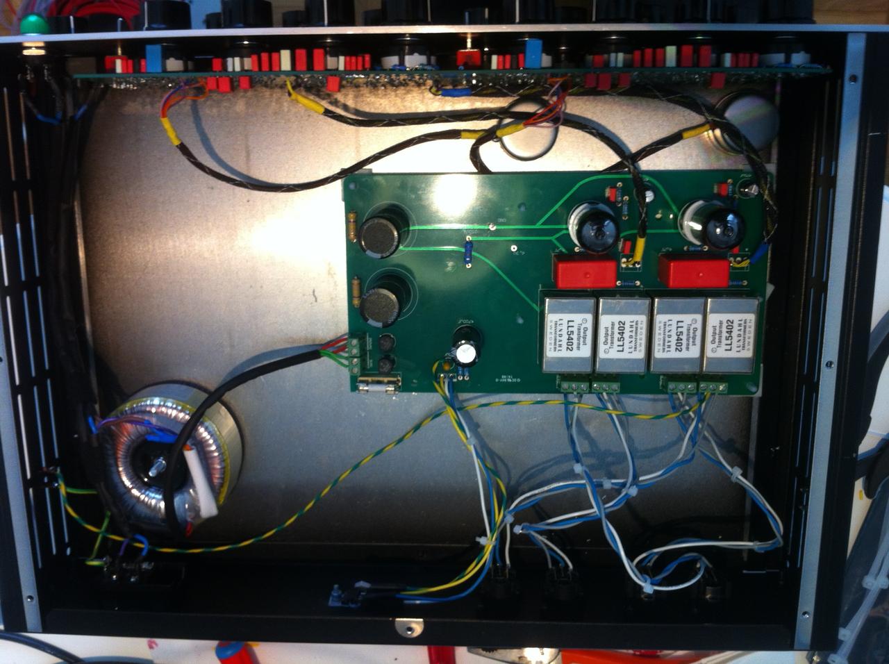
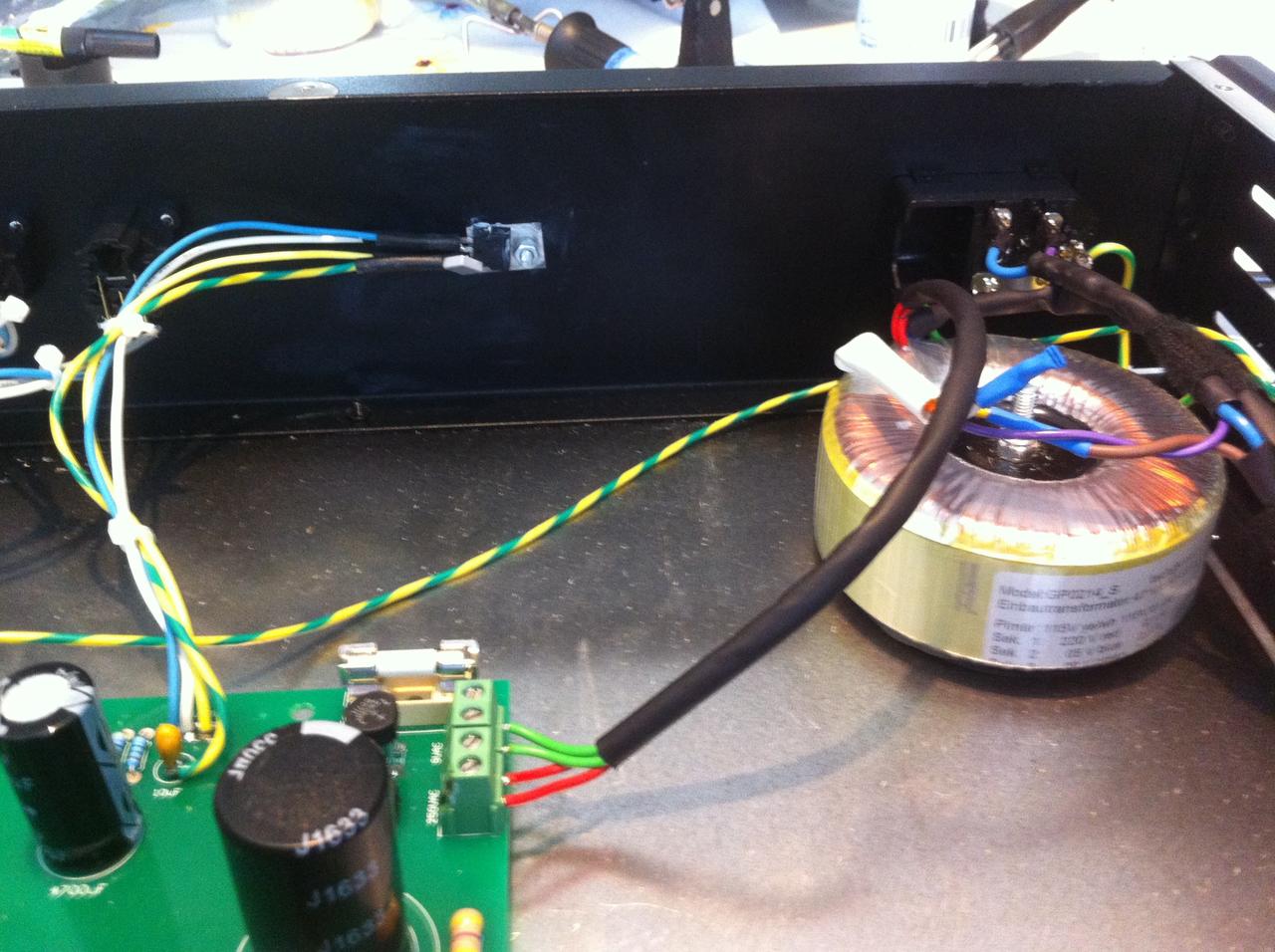
I still have no time for troubleshoting...but im thinking my problem is in grounding. When i conect xlrs PIN 1 to PCB, bridge rectifer get very hot in few seconds.
M.
M.
Vac11 said:I still have no time for troubleshoting...
Lieto said:Hi Gustav,
thanks for you're fast reply. I used the W04G-E4/51 Diode with 1.5A at first and the unit runs more or less fine (except of a gain loss around 10dB). Then I mess around with the LM317 and the diode bridge gets toasted... :-[ I replaced the W04G with a 2W06G Diode (2A 600V). Maybe you're right, the transformer can provide 2.5A on the 9V. But the ECC88 needs only 300mA.
Which diodes do you use Gustav?
My tubes are fine so far, the heater works, got round about 6.1 V 8)
Thanks for you're help! Regards Andy
Gustav said:No particular diodes. Just wanted to verify that you were using a diode with the capacity to handle the current flow as a start.
6.1V on the heater checks out. .
Since you report the unit to be working before heat sinking the LM317, I'd guess you ran into trouble there, but now you are reporting a 10dB loss before doing so, so its possible, theres another problem with the build.
Did you isolate the LM317 from the case when you mounted it to the case for heat sinking?
Whats your high voltage reading? Before and after the drop resistor.
- also be aware, you can check the filter separately. Signal to input pin on the filter, check signal on output.. there will be a drop, but you can check it none the less, and isolate any problems to the gainstage 100% by doing so.
Gustav


Lieto said:no I didn't isolate the LM317, maybe this was the Problem.
Gustav said:Yes, definitely a problem.
Not sure about the mods you are doing shouldn't be necessary to build the unit with no kinks at all.
Gustav
relurelu said:Hi, guys, I got my V.1 board. I got it without any BOOM, documentation... The big caps from the valves board is unknown for me, bleeder is a new thing for me... bridge values... Maybe I will find more. Maybe somebody is good to upload or link to your documentation.
leo-666 said:Hello, Gustav.
I did not want to post this question to the topic since it's a noob question.
Hoped to get your direct answer.
But seems like your private inbox is full.
Amazing project.
But I'm a bit confused about switch resistor values.
I downloaded PQD2switches-kit.xlsx file.
Where to find needed values ?
PCB layout states about 100 needed ones around the switches as I understand.
And one more question about inductors.
I've chosen a goal to reach 1% tolerance between channels.
And I did not find good 1% matched fixed inductors at Mouser.
So I ordered Don Audio ones.
https://www.don-audio.com/G-Pultec-Inductors-matched-pair-22mH69mH169mH269mH
They're ok ?
At first I was confused with different induction 22mH,69mH,169mH,269mH.
But then understood that it's a different abbreviation.
22 + 47 + 100 + 100.
22 = 69 = 169 = 269.
So seems like everything is ok.
Best regards...
leo-666 said:
leo-666 said:Thanks, Gustav.
Still quite don't get it. Sorry.
This is not my first build, but certainly more complicated than the previous ones.
And without simple insctructions I won't be able proceed to Mouser cart.
For example, we take resistor A9 or F9 that belongs as I understand to the right column. (Low cut)
What resistance to choose ? 91000, 21000, 21000, or 91310 ? To say simpler, what column to look in ? (
Same for B4/G4. 862, 278, 280 or 863R ?
And about HiQ, HiCut and HiBoost dividing by ten. Absolutely can't understand this.
I.e. Hi Cut, we have 100R stated.
How it must be divided or multiplied to achieve 10 different values ?
Thousands sorries for my stupidity )
rprimmett said:Hey guys, I have two of these to build and am super excited. I'm going to be using Edcor XS1100's and am wondering if I could also get a power transformer from them too. I open to some suggestions for the power transformer but at the least need to know what kind of current the 250V and 9V will be drawing.
Enter your email address to join: