[BUILD] VC528 ST2+ 500/51x Support Thread...aka The Missing Link!

GroupDIY Audio Forum

Help Support GroupDIY Audio Forum:

This site may earn a commission from merchant affiliate links, including eBay, Amazon, and others.
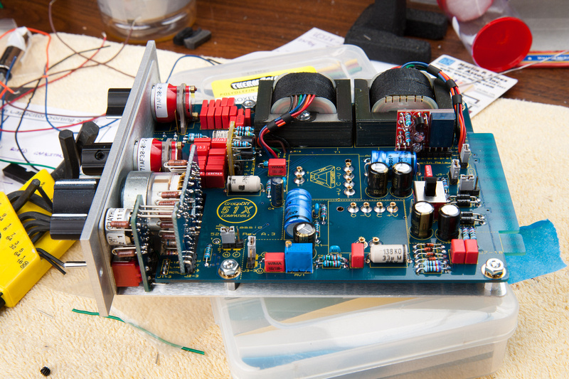
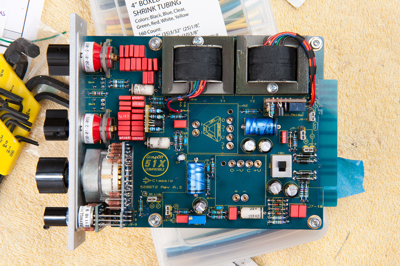
This unit still needs to be calibrated when I can get to the DAW in the studio and I presume I will need to make a harness to hook it up outside of the rack for that.  For now, I hooked it up uncalibrated to a p-bass just to see if it would pass audio and all appears to be running great.  Controls all function as expected.

Taking my time, reading the assembly guide, and double checking everything before assembly appears to have paid off.  Well, it's either that or actually understand what I'm doing  :eek: :eek:
 
Good things come in pairs. . . finished assembly of the matched 2nd channel  ;D  I will calibrate them both together, but need to put together 1 more GAR2520 tomorrow to complete it.

p566566910-4.jpg


p881777339-4.jpg


. . . a little more casual with the pics and a much faster build the 2nd time through.
 
Ok. . . back to it. . . a few logistics need to be figured out in order to calibrate the VC528's in studio.

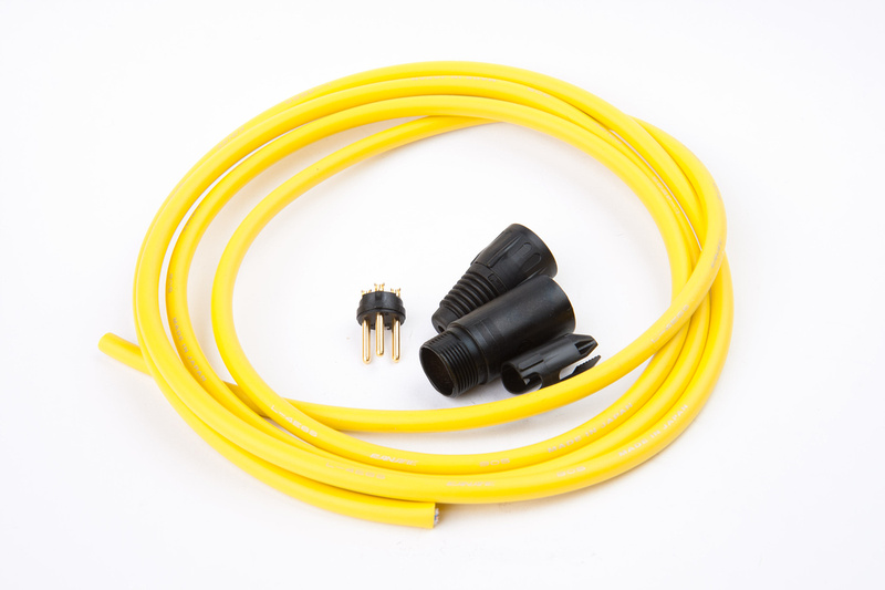
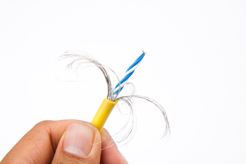
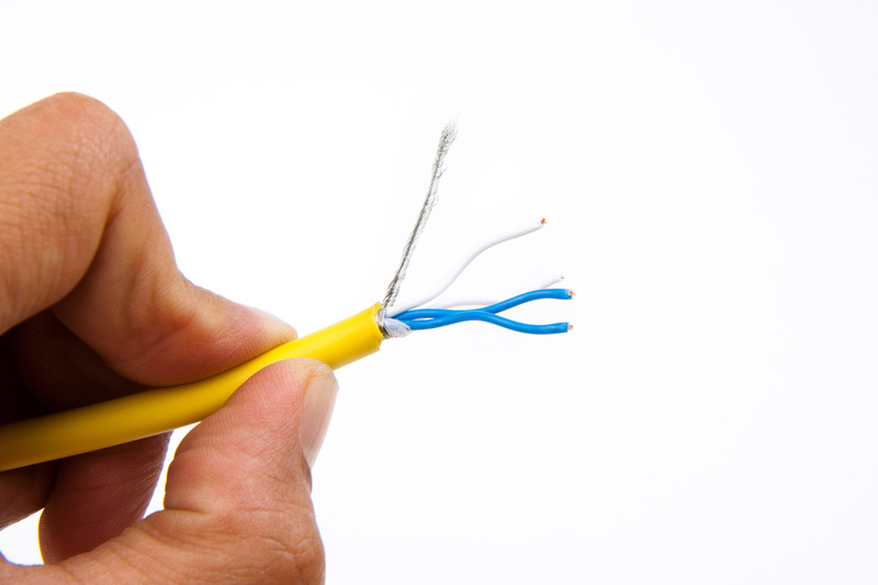
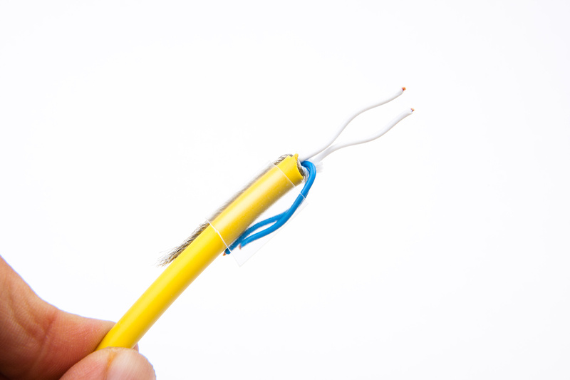
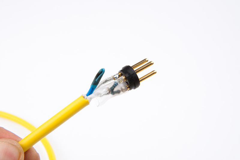
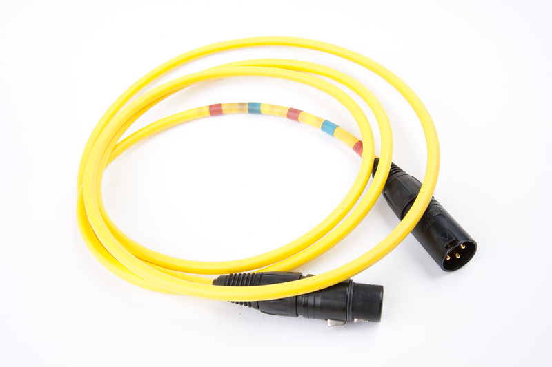
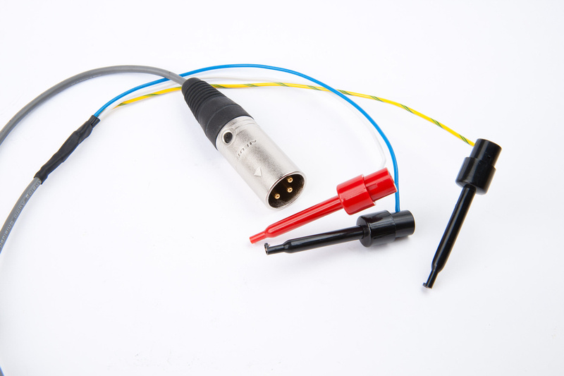
First, the calibration cable.  Detailed instructions for assembling this cable are included in the build documentation.  Here is my attempt.  It did not turn out as clean as i would like, but functional.

p76511216-4.jpg


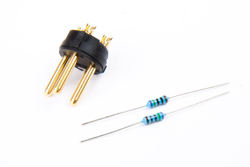
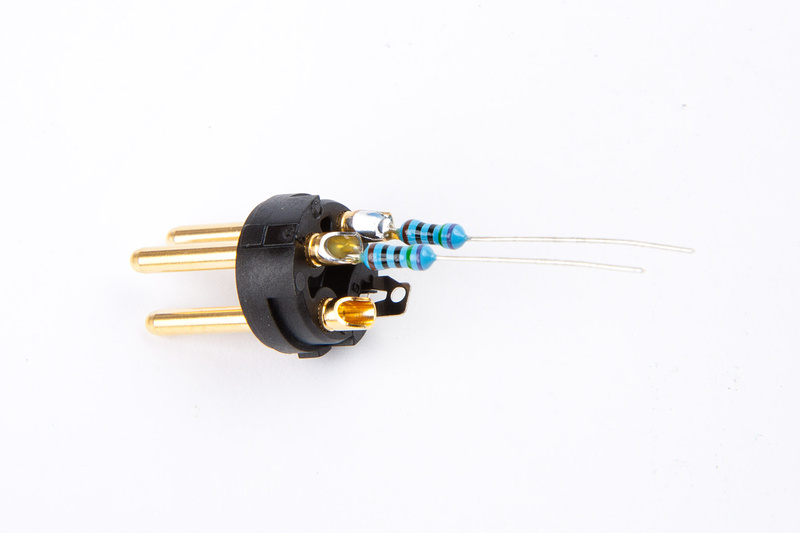
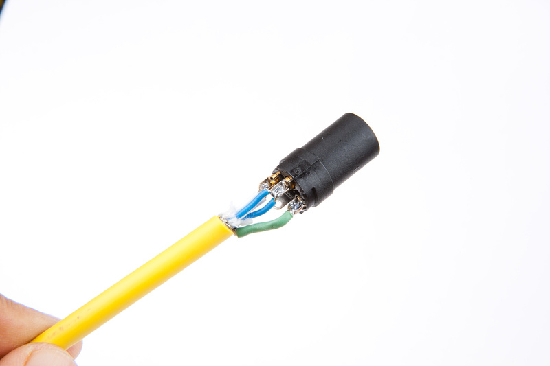
This is the end that will be different from your ordinary mic cable.  I am using 2 VERY tightly matched (.1%) resistors.  This is important.  The value of the resistor can vary.  Any value between 100 ohm and 1K ohm will do the job.  These are 750 ohm.

p86133225-4.jpg


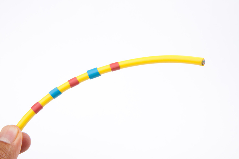
In order to differentiate this cable from the others in the studio, I used some creative shrink tubing.  This will certainly be a clue that something is different about this cable and trigger the recollection that this is a calibration cable.

p402289108-4.jpg


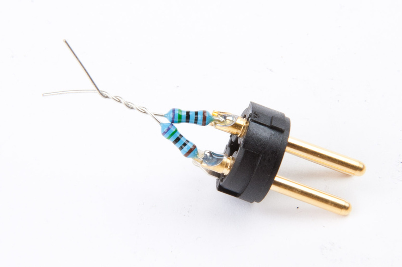
Next, I solder the resistors to pin 2 and 3 of my male XLR connector.

p109390642-4.jpg


. . .and twist the end together.  Pin 2 from the female end will connect to the resistors here.

p215602644-4.jpg


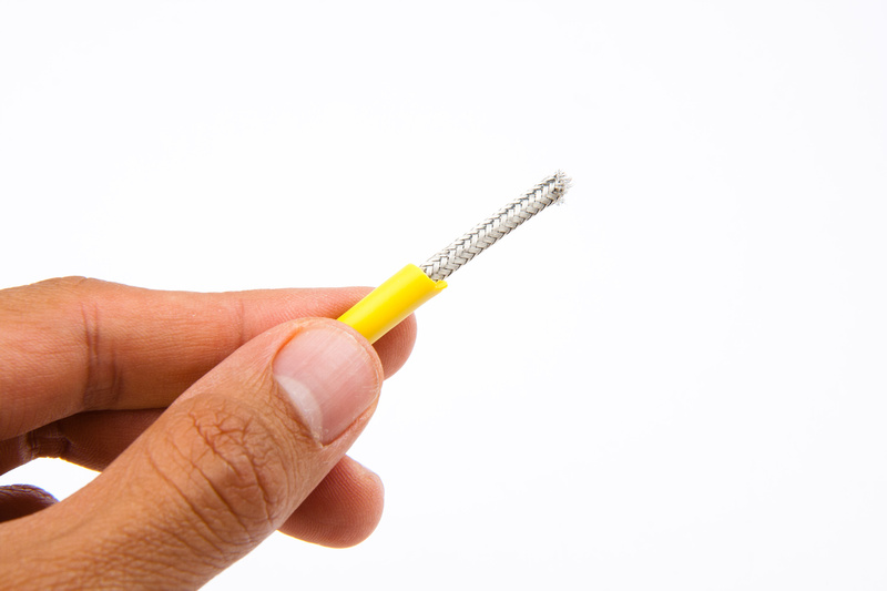
I'm using Canare L-4E6S cable. . . which is a bit of a pain to work with, but I think is good sounding stuff.  Probably completely unnecessary in this application, but this is the only mic cable I had around at the time.

p83678204-4.jpg


p163754152-4.jpg


p96528809-4.jpg


Trying to figure out how to keep the mess from shorting.  Not my finest DIY moment, but I think this will work.

p487932866-4.jpg


p179785986-4.jpg


The difficult end is done, and the other end wires up as normal.

p529547005-4.jpg


Calibration cable complete!

p239449084-4.jpg


Next, I need to figure out how to get this unit powered up and input/output functioning outside of the rack for calibration.  There are many ways to do this, so I thought about it for a while.  This is probably something I will need to do with other future modules, so some good tools would help.

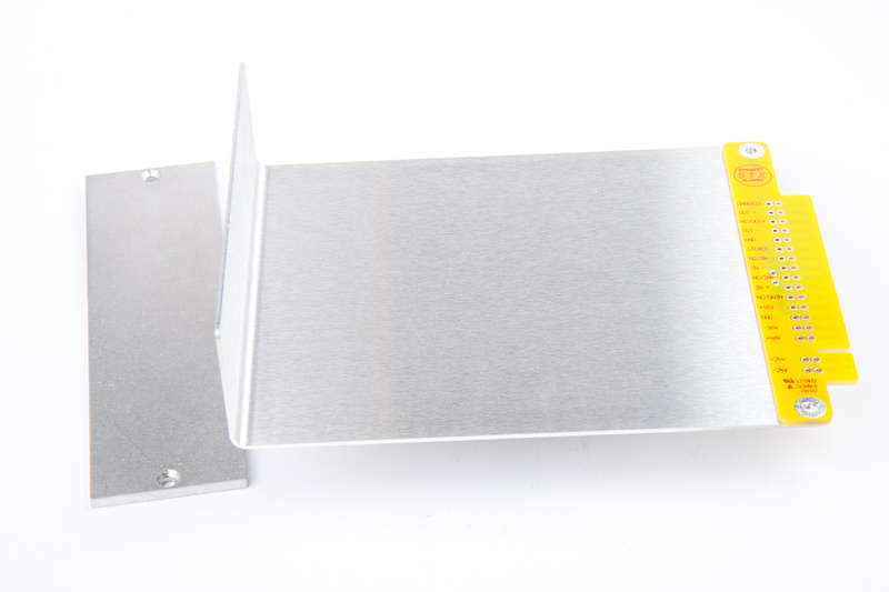
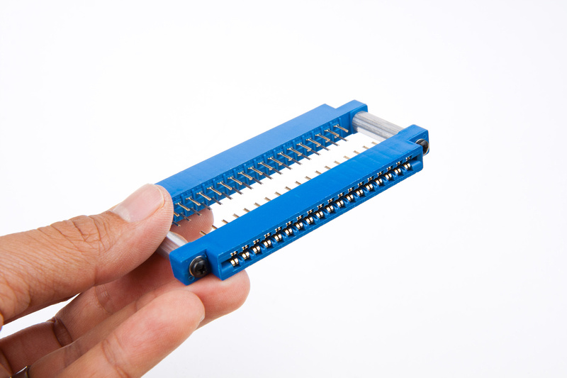
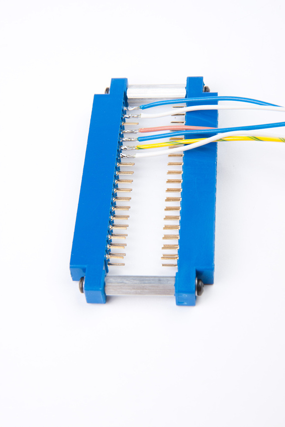
First, I thought about just creating a 51X card that is merely a pass-through "umbilical" connector.

p413927849-4.jpg


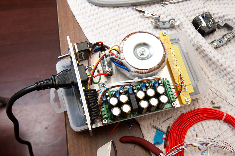
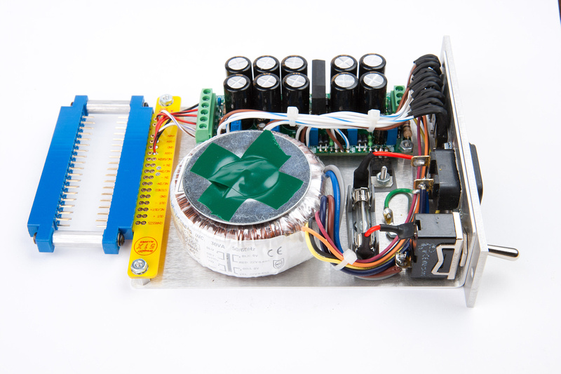
Then, I thought about utilizing a little 51X "plug-in" power supply I had rigged up with a JLM powerstation prior to the official powers supply kit being available in the United States.

p76301878-4.jpg


Luckily, I had purchased some DIY supplies and spare parts to have in my bin for situations like this, and came up with something I thought might do the job more elegantly.

p305617449-4.jpg


p215959713-4.jpg


My initial thought was to jumper straight across for an easy build, but then, I realized the modules would have to be inverted from each other to work, and the handling may become awkward.

p43263749-4.jpg


p177240355-4.jpg


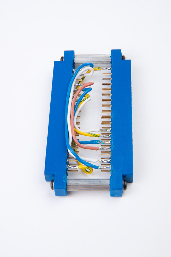
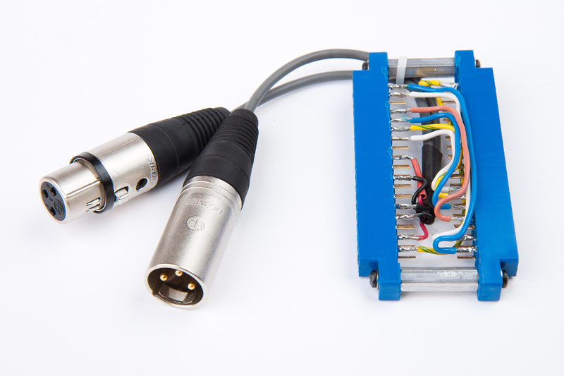
So, I abandoned that idea and decided to wire the adapter so the modules could both orient face up which basically means connecting all wires to the opposite end.

p399883771-5.jpg


p126382008-5.jpg


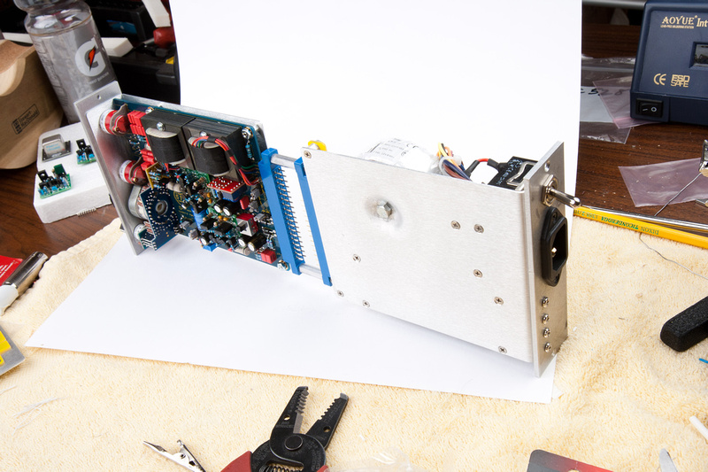
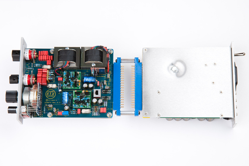
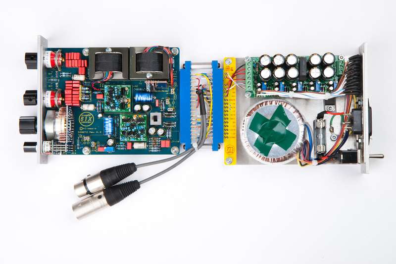
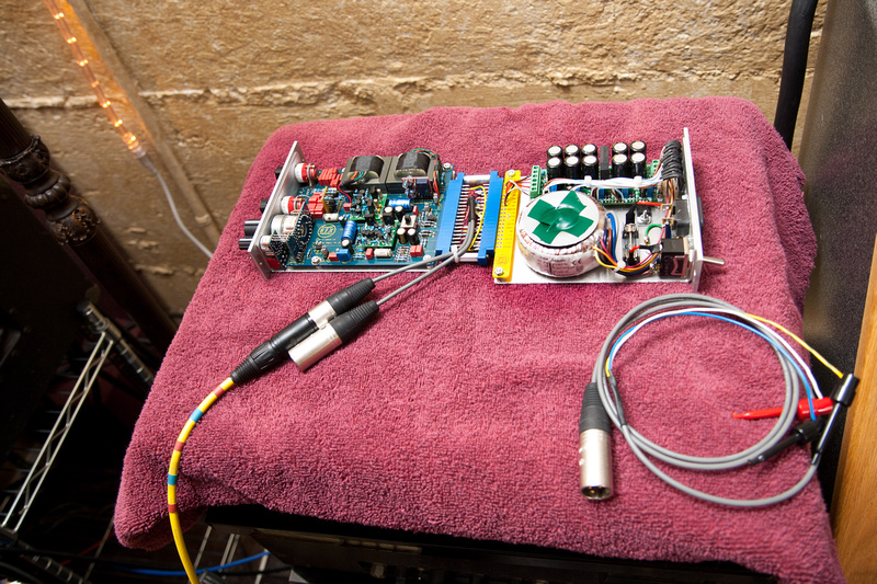
And, this is what I ended up with. . . powersupply goes on the right side, and the VC528 goes on the left side w/ the main input and output connectors spliced in for easy connection.

p212384525-4.jpg


And, all hooked up. . .

p417433630-4.jpg


This is looking like it might work for when I bring this into the studio to calibrate.  One more small item remained, and that is an XLR cable with test clips on one end to clip onto specific leads on the PCB.  Again, digging in my parts bin, I come up with this.

p467839677-4.jpg


Now, I am really ready to get these VC528's dialed in, and hopefully have some simple tools that I can re-use for calibration and testing on  other modules I assemble.


Nice thinking 'Chung! I love the back to back modules with your special PSU. This will make calibration easy for you.  8)
 
mulletchuck said:
Chunger you work too hard!!  Just take off the right side and top of the module rack and put the vc528 into the right most slot lol.  Nice pictures, tho :)

like this:

http://img854.imageshack.us/img854/4865/imag0094my.jpg

Can't do it if I can't take a rack off-line.  Cost differential between a JLM powerstation + small transformer and a full 11x rack kit is huge.  This will let me test modules on the bench much more easily.

Oh, on the off topic, we were going to try and DIY (homebirth) this one as well, but it appears she had other plans (resolutely in breach position).  So, we had to go 1 hour away to a hospital that would deliver natural backwards babies.  Further updates may be delayed for a little while.  Reason below:

p911599109-4.jpg
 
Congratulations 'Chung!! That is awesome. I am very happy for you and your family!! Soldering may have to wait for a few decades.  ;) :)
 
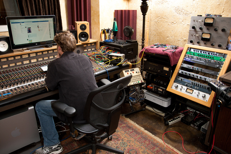
OK. . . new baby has been sleeping very well ~3-4 hour stretches, so I was able to get out to the studio to calibrate the 2 test modules.  Please excuse the step-down in photo quality.  I was busy trying to get these things calibrated and most interested in HEARING them.

p867150818-4.jpg


And my tools deployed.

p1061975986-4.jpg


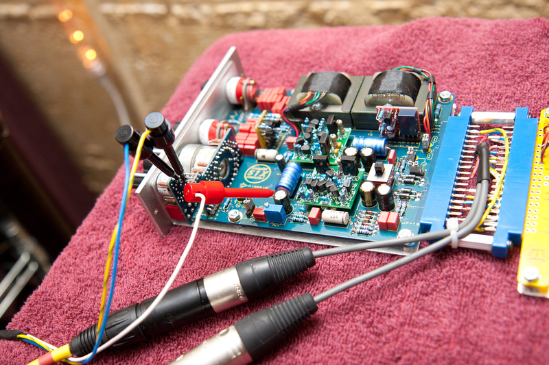
probes placed and adjustments being made. . .

p743525985-4.jpg


. . . according to the detailed instructions provided, I feed a 400Hz signal to the input through my special cable w/ matched resistors.  Then, I output directly into my A/D converter (apogee Rosetta in my case) and monitor the output off of my little clips on the PCB as pictured above on a metering plug-in in Logic (or any other DAW).  I turn the trim pot clockwise quite a few turns and then i see the levels drop.  Once I find the lowest point, I lock my setting in by painting the trimmer pot with some nail polish.

I'm running Gary's GAR2520's in these VC528's because that was the opamp that jsteiger suggested I run.  From reviews of the VC528, it seems the GAR2520's are a great "standard" opamp for these if you are looking for something with some flavor but pretty down the middle for "general use".

The sonics on these units was pretty incredible.  There are very few pieces of gear that I would envision using ALL THE TIME, but inserting these onto my main LR mix bus, bumping the level up ~4dB was so awesome I really don't see a reason not to leave it there pretty much forever.  Added a bit of weight to the mix, gave me some harmonic dimensionality, and made everything a bit punchier in a very refined way.  I do not see audio devices of this pedigree anywhere near the cost of entry.

This was not a unit that I would have sought out on my own, but when Jeff asked me to do some official documentation photos for this project, I looked at the likely applications and said to myself, "This really needs to be a stereo pair."  Having played with them for a short test session, I feel very validated in that decision.  I have yet to play with these in tracking, but I would encourage fence-sitters to experience these in multiples of 2 especially because Jeff matches many of the critical resistors to .1% on the stereo bundle kits.  The likely stereo applications are too numerous IMO to do just 1.  The mute linking via pin 6 is also pretty trick:)
 
When I crank the output of my kits into this box, it responds almost like a compressor, with a pretty high ratio and a quick .1 attack.  Its a great kit, especially as a final fader/gain stage before going in the box.  The high pass filter sounds amazing too.  I live on the top floor of a building with a restaurant on the ground floor.  The vent fan for the kitchen is above us, on the roof and shakes the whole place.  The 80hz 12db filter cuts all of it out!  Super smooth, creamy filtering.
 
chunger said:
Oh, on the off topic, we were going to try and DIY (homebirth) this one as well, but it appears she had other plans (resolutely in breach position).  So, we had to go 1 hour away to a hospital that would deliver natural backwards babies.  Further updates may be delayed for a little while.  Reason below:

congratulations chunger!  enjoy your new diy (and i mean the baby) ;D 
and also congrats on the new VC528 ST2+ build.  nice documentation as always.
best,
grant


Back
Top