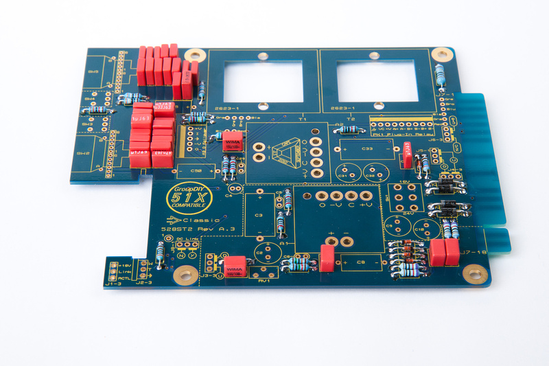
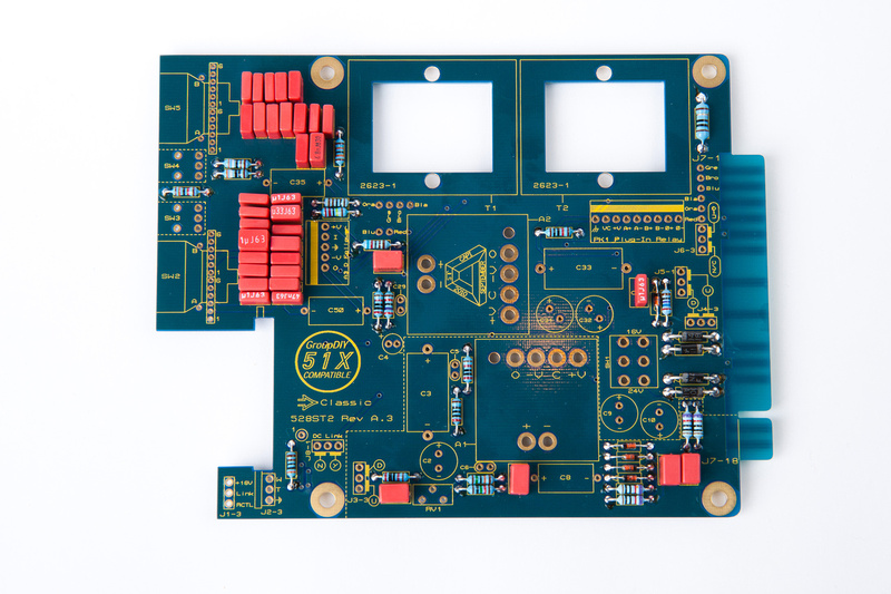
[BUILD] VC528 ST2+ 500/51x Support Thread...aka The Missing Link!

GroupDIY Audio Forum

Help Support GroupDIY Audio Forum:

This site may earn a commission from merchant affiliate links, including eBay, Amazon, and others.
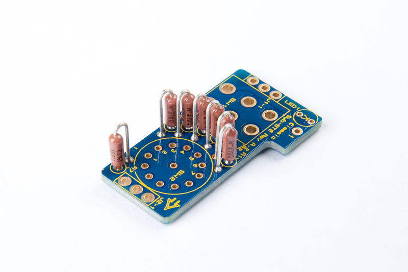
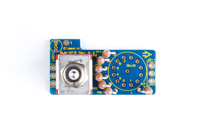
Next on the menu is the sub-ST2 board.  Details about this board can be found in:

"8_04-1x24 Rev A_Sub-ST2 Rev A.2 Overlay.pdf"

and

"7_Classic VC528 Sub-ST2 PCB BOM.pdf"

in the build documents.

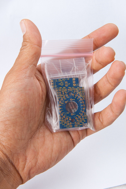
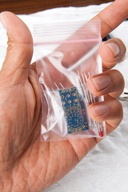
The components for the Sub-ST2 board can be found in this baggie:

p678690104-4.jpg


Note, in the stereo kits, you'll find 2x pcb's and a closely matched set of resistors in this baggie.

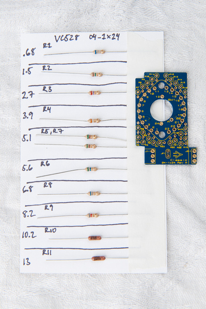
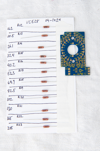
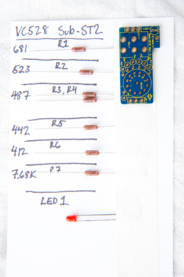
Next, I identify and sort the electronic components.  For our build, even though I'm doing a stereo pair, I'm showing components for a single  board in the photo. . . just to keep things consistent.

p679369312-6.jpg


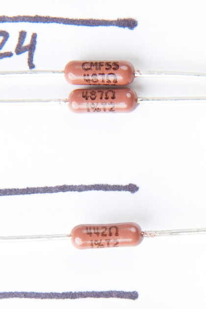
These resistors are very easy to identify because the values are all printed at a pretty reasonable size.  I double check them all with my multimeter just to be safe.

p1059516465-4.jpg


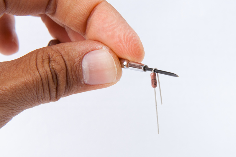
Here's a little trick I learned from the draft instruction PDF jsteiger wrote up to make clean, consistent bends on the resistors using the shaft of a small screwdriver.  Worked great!

p602163764-4.jpg


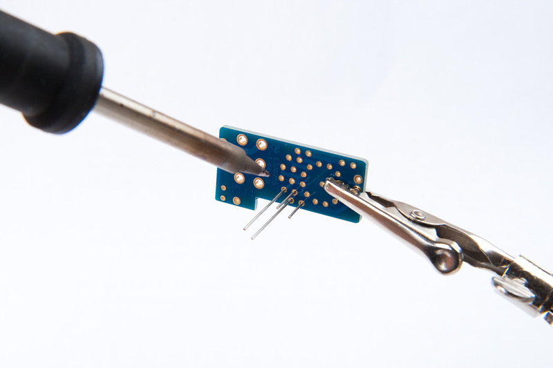
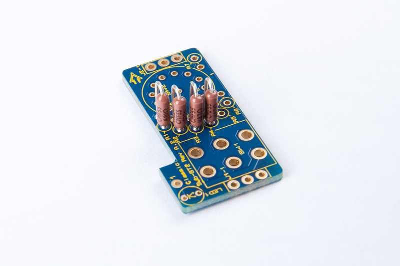
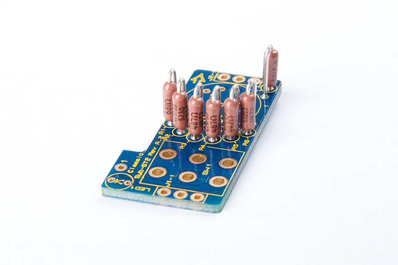
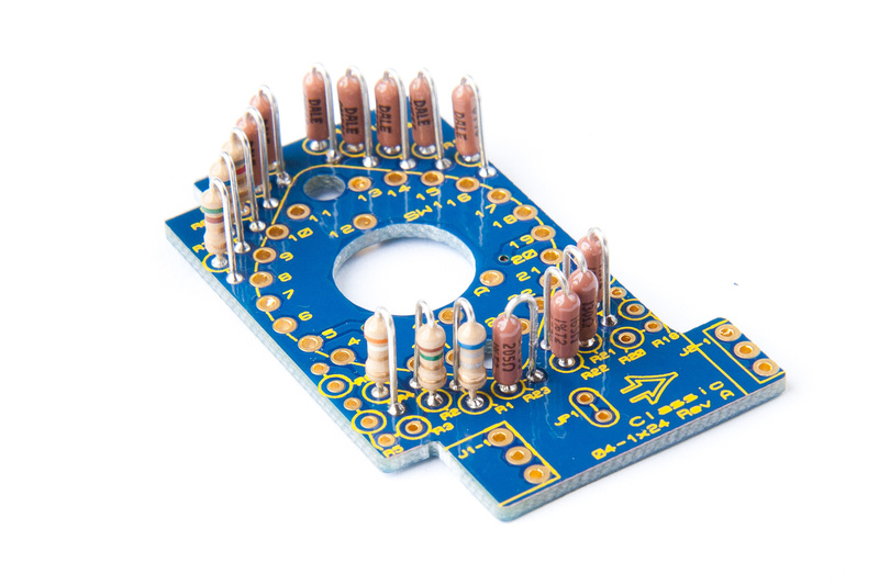
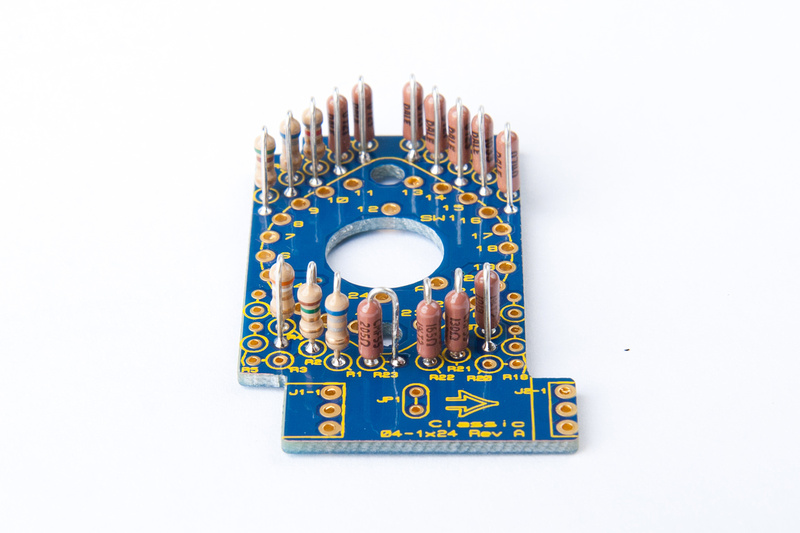
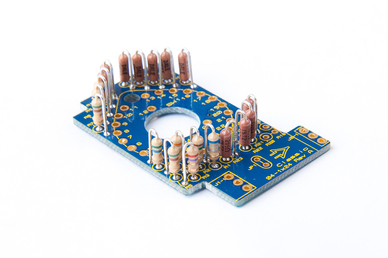
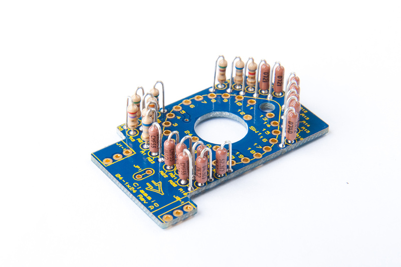
and, we're populating.

p805787883-4.jpg


p919620537-4.jpg


p577304100-4.jpg


and, a shot showing my resistor values more for personal reference later if I have a problem.

p941486962-4.jpg


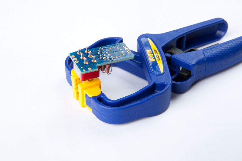
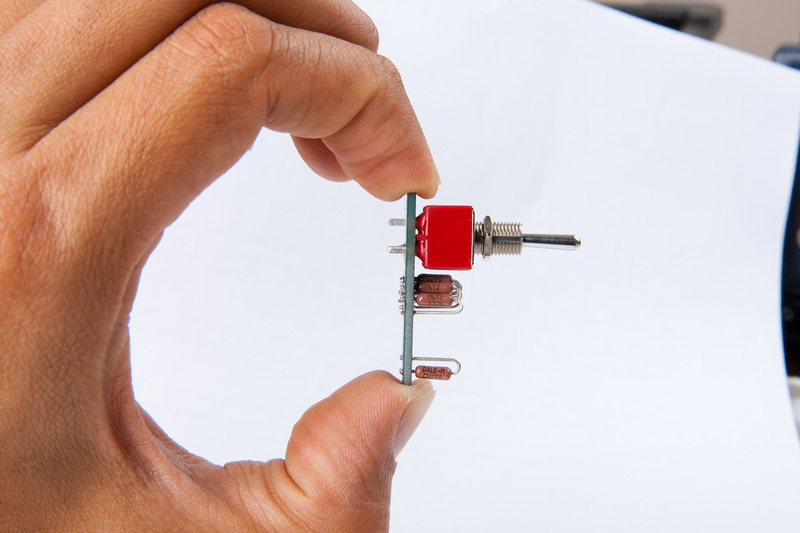
Next we install the 3 position toggle switch. . . the instructions say to make sure and seat this one flush to the PCB and straight.  I lightly clamped the threaded shaft of the toggle switch like so. . .

p801845701-4.jpg


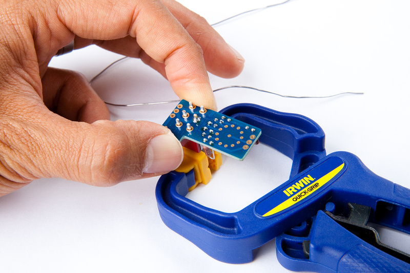
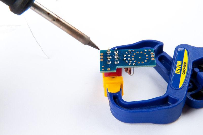
Then, it was a bit of a juggling job, but not too bad.  I chose one of the center solder lugs, pressed down with the soldering iron lightly and soldered the joint. . . immediately when the solder melts into the joint, and with the soldering iron still on the joint,  I let go of the solder wire, and press the PCB down firmly with my fingers. . . easy.  Then, remove the soldering iron and hold the joint until the solder hardens.

p724639168-4.jpg


It would have been awesome to have a picture holding the PCB with my left hand, and with the soldering iron actually on the joint, but it was logistically difficult having only 2 hands  ???

Verify that everything is fully seated. . . nice and straight:

p817236979-4.jpg


doesn't get much better than that, so I went ahead and soldered the remaining lugs on the switch.

p670850185-4.jpg


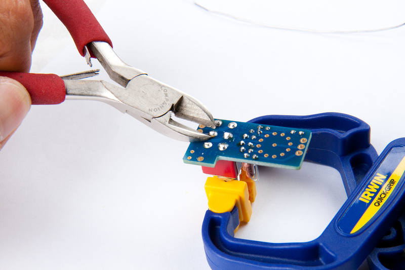
Then, per the instructions, I cut the leads on the switch close to the PCB

p618899650-4.jpg


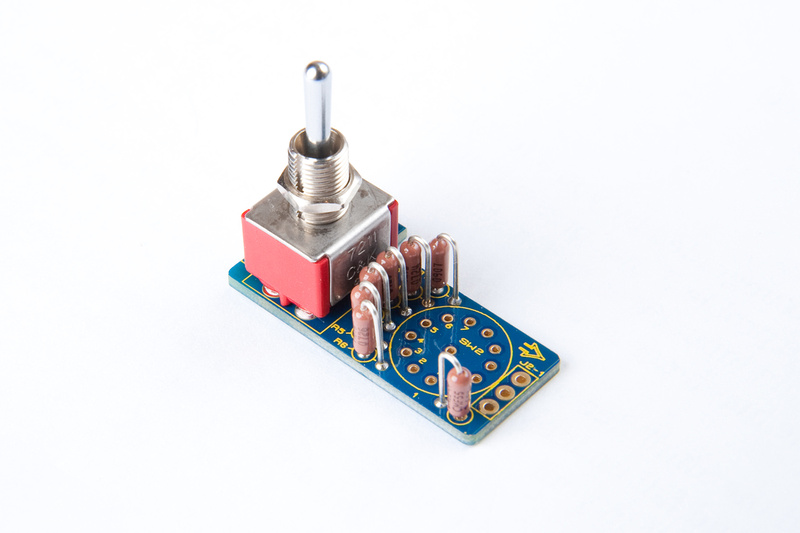
OK. . . instruction set says to leave the L-header, LED, and Grayhill switch off for later steps, so we are done with this component for now.
p794144443-4.jpg


p566768464-4.jpg


Something I forgot to mention before... I do not recommend using a freshly built DOA in the receiver stage during the CMRR adjustment, unless you are 100% sure the opamp is functioning correctly. A stable and correctly operating DOA is a must for the CMRR adjustment to be right!

I added the above note to the first post. I should have thought about mentioning that before.  :-[

Cheers!  :)
Jeff
 
Sorry about the delays.  A little more progress tonight.

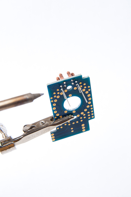
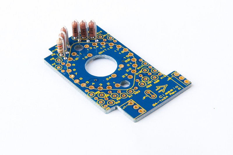
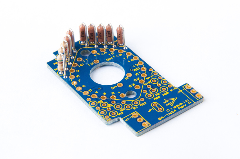
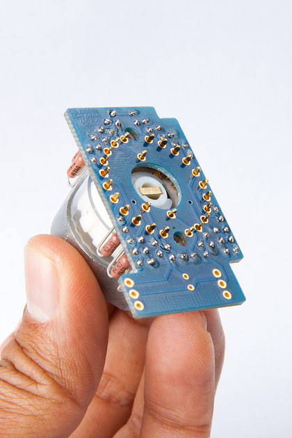
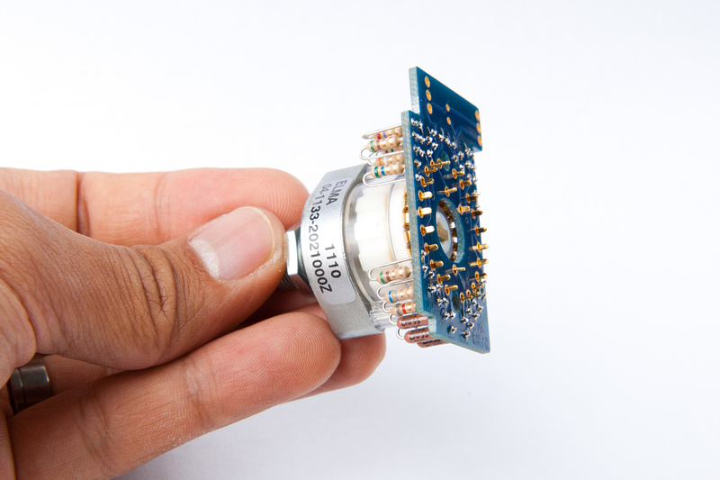
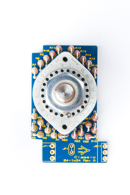
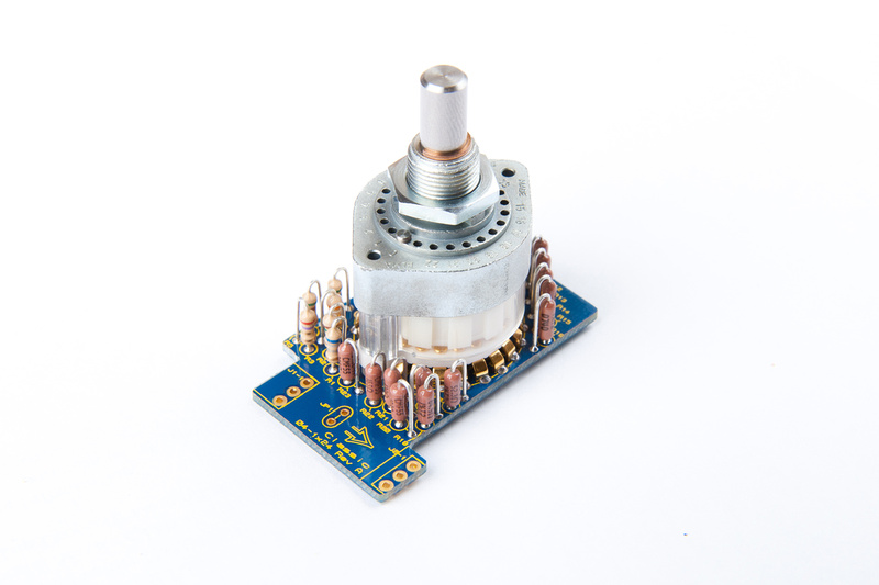
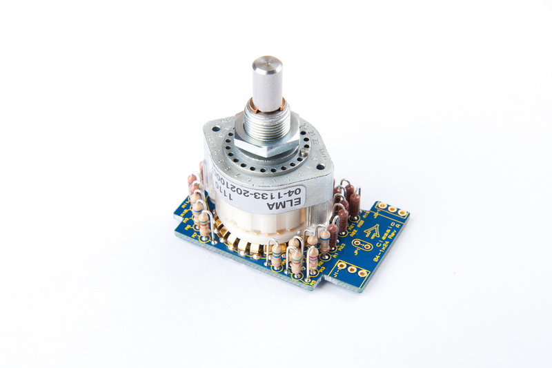
Next up in the build is the Elma switch sub-board.  The parts are contained in this baggie:

p1067564030-4.jpg


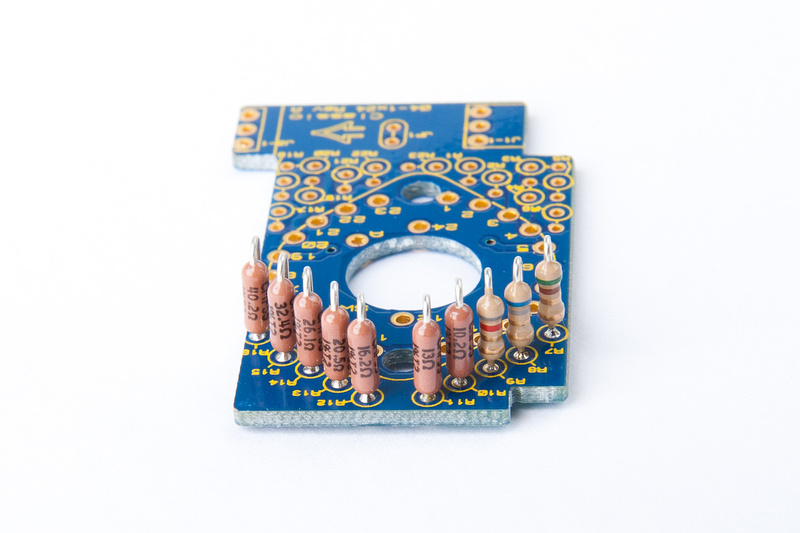
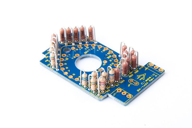
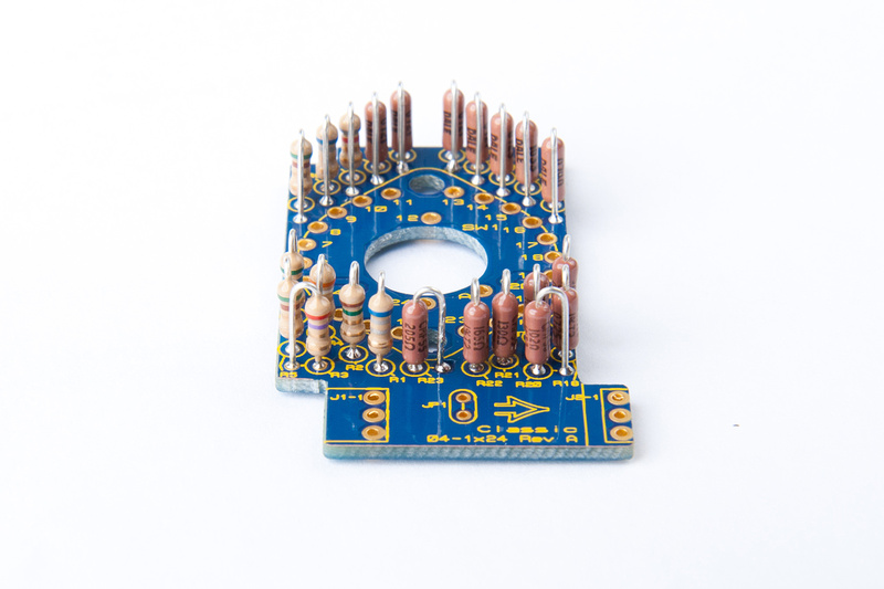
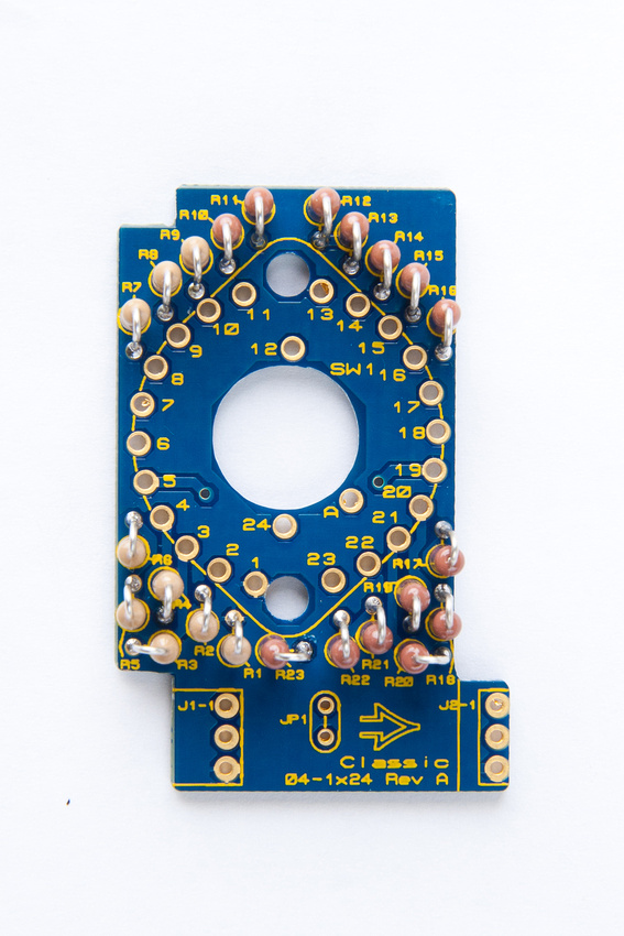
There are a lot of resistors to sort in this little board.  Here are the parts identified, sorted,  and ready to go.

p569048016-4.jpg


p541675721-4.jpg


and, we're populating in the order specified in the build manual. . .

p773058455-4.jpg


p883651993-4.jpg


p916836964-4.jpg


p711824672-4.jpg


p851113204-4.jpg


p714520449-4.jpg


p827971819-4.jpg


p1013246646-4.jpg


and, all resistors are placed.

p884664457-4.jpg


p755689503-4.jpg


p657894603-5.jpg


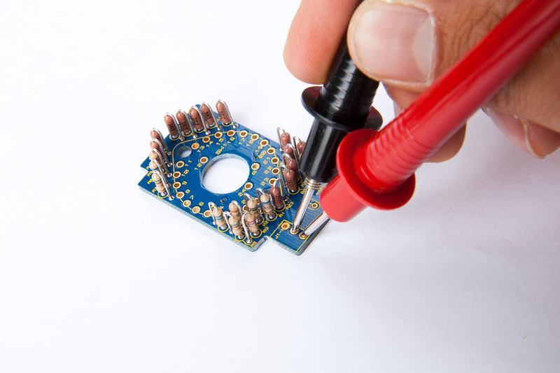
Next, I check resistance between J1-2 and J1-3 looking for 1K ohm to make sure I did not bridge any solder joints.

p735710188-4.jpg


and we're good to go.

p1011158034-5.jpg


The Elma switch is placed. . . a few pins needed to be slightly nudged into position before pressing into the PCB.

p838478102-4.jpg


p562574834-4.jpg


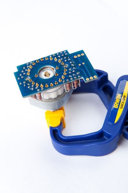
And, here is how I set up to solder the switch

p969238687-4.jpg


And, Elma switch is in.

p897516484-4.jpg


p808309734-4.jpg


p1052147345-4.jpg


I checked resistance again between J1-2 and J1-3 to confirm we are still at 1K ohm, and this sub-assembly is ready to go.  We set it aside for now.
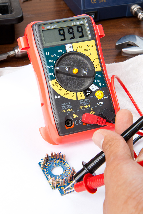


i finish my VC528 ST2+ ( thanks chunger , your pics and advices are very useful)  now i need calibrate but i'm a little confused what i need apart of the resistors and the tone generator (  i have here a DMM and the resistors only  :-[), or maybe is another way ( more easy) to do it this step ?

Some pics:

http://www.flickr.com/photos/mar1o_bross/sets/72157627033770651/
 
sea_man, you can use your DAW as a generator. You can also set an input of your DAW to record ready and then monitor those levels during the calibration process.
Besides the cable with resistors, you only need 2 other things. A signal generator of some sort and a device to monitor the output level of the receiver amp. Can be a DMM, scope or DAW inputs.

A very important thing is to use a known, good DOA in the receiver stage when you make this calibration.

BTW, nice pics!  ;D :eek: 8)

Cheers, Jeff
 
Done ! Whit a little of patience , a digi 003 , and many cables and alligator clips my first unit reach -72.1 and the second -71.8 dbu !

Thanks again for your help !

 
sea_man said:
Done ! Whit a little of patience , a digi 003 , and many cables and alligator clips my first unit reach 72.1 and the second 71.8 dbu !

Thanks again for your help !


Your gonna love them!
 
I was wondering about 'Chung as well. From his Facebook updates, I think he may be buried under the sand on a volleyball court at some beach.  :'(
 
I have built two of these vc528's and they sound incredible.  "The missing link" says it all. Great work on these Jeff! Also, thanks for the pictures as these were a great help during the build.
 
Daniel Ovie ask me if I had a recall sheet prepared for the VC528 module. My answer was "no" but now I can say I have whipped up 4 different ones. These links have been added to the first post of this thread as well as the product pages at my site.

************************
Recall Sheet pdf downloads:
1 module
2 modules
4 modules
6 modules
************************

Cheers, Jeff
 
Ok. . . sorry about the extended delays, folks.  Trying to get ready for 1st baby coming late October, so my workspace has been in chaos.  So, little progress today, but onward none the less :)

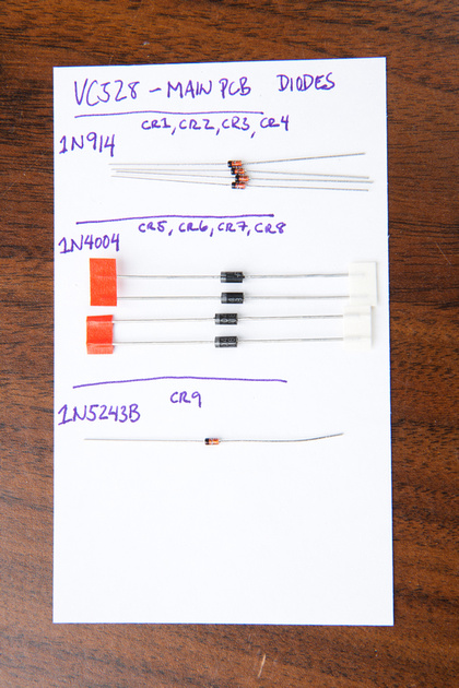
Time for the main PCB.  Time for a little parts identification. . . diodes are up.

p507041359-4.jpg


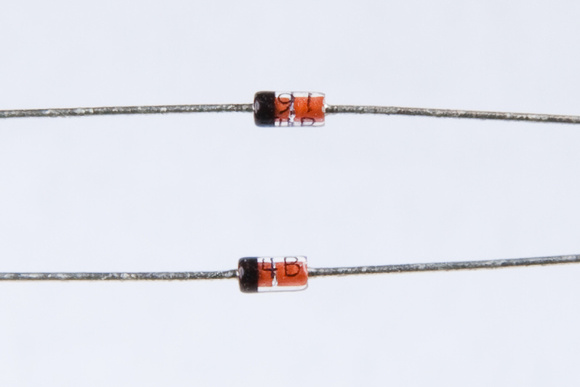
Watch out for the 1N914 CR1, CR2, CR3, and CR4. . . these look like this:

p775789131-3.jpg


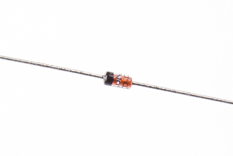
Also, watch out for 1N5243B CR9. . . it's marked:

24
3B

p328308671-4.jpg


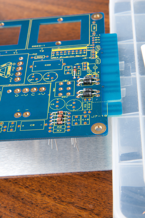
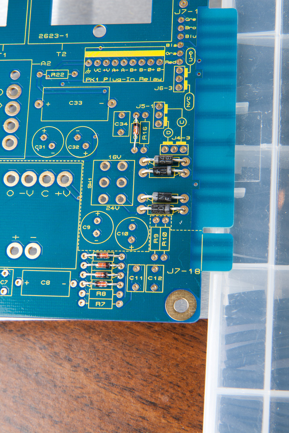
Next, I placed the components on the PCB as marked.

p154927727-5.jpg


p463005680-5.jpg


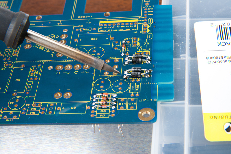
And, soldered the components in from the top side.

p261292798-4.jpg


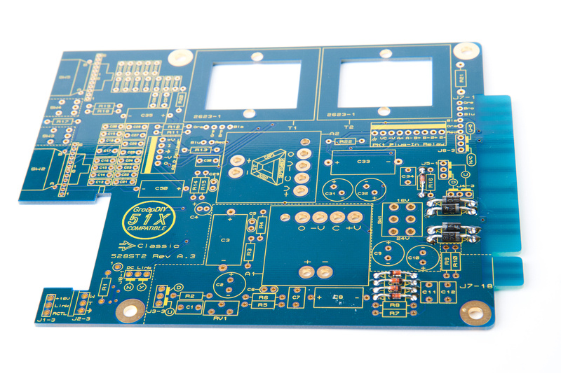
And, diodes are done.

p192773095-4.jpg


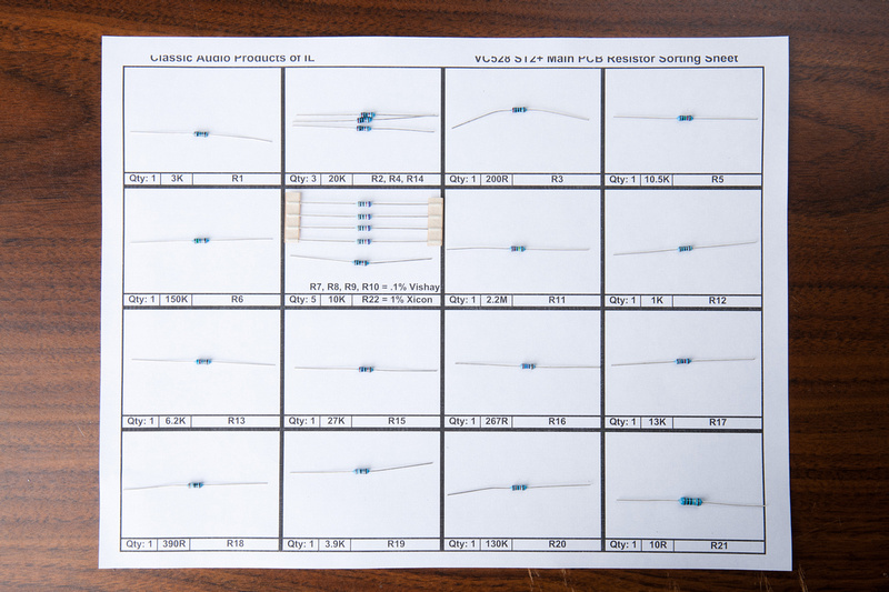
Next up, I use a printout of the provided resistor sorting PDF to sort the main PCB resistors.

p252368537-4.jpg


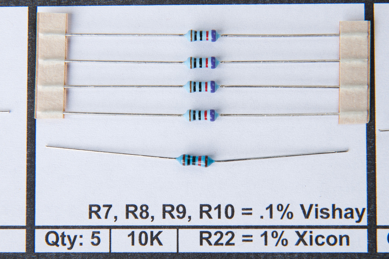
Note: R7, R8, R9, and R10 are packaged together and are .1% Vishay. . . R22 is the same value, but 1% Xicon

p243513705-4.jpg


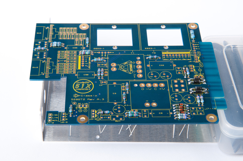
I then place all resistors on the PCB.

p376228237-4.jpg


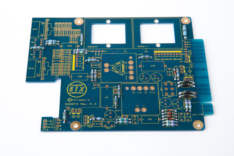
and solder from the top side cleaning up joints as needed from the back side.

p318603265-4.jpg
 
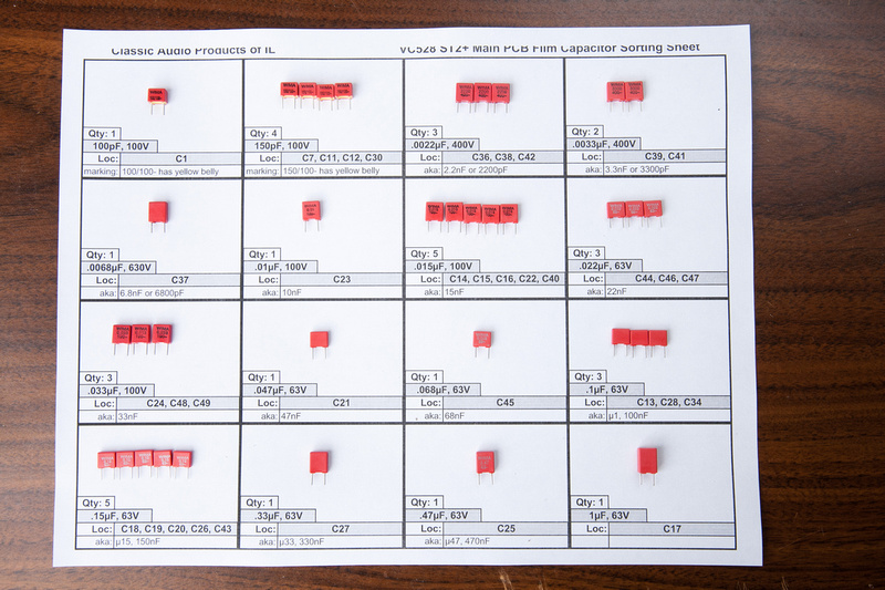
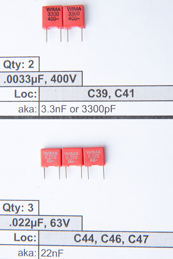
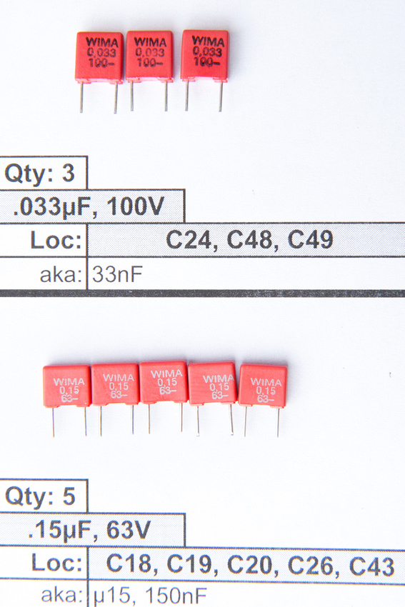
Next up, I use a printout of the provided film capacitor sorting PDF to sort capacitors.

p878930614-4.jpg


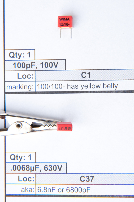
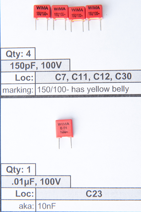
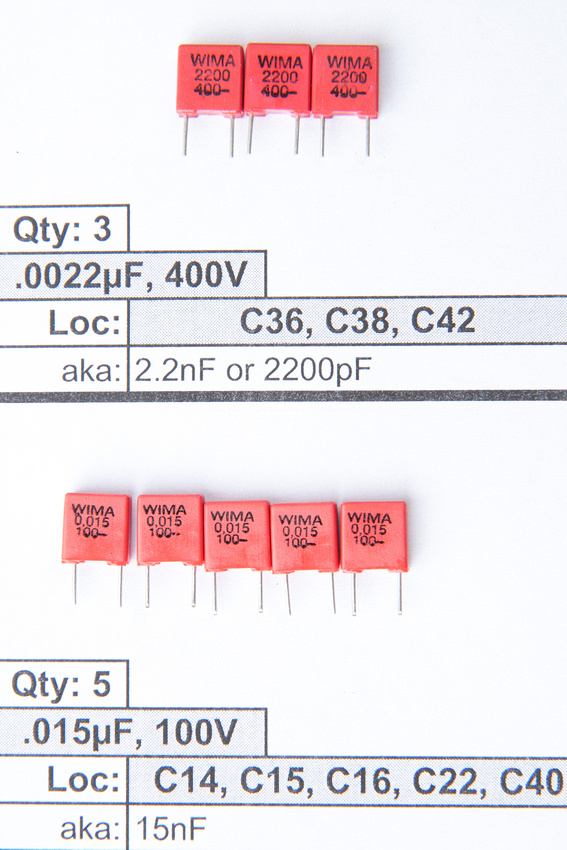
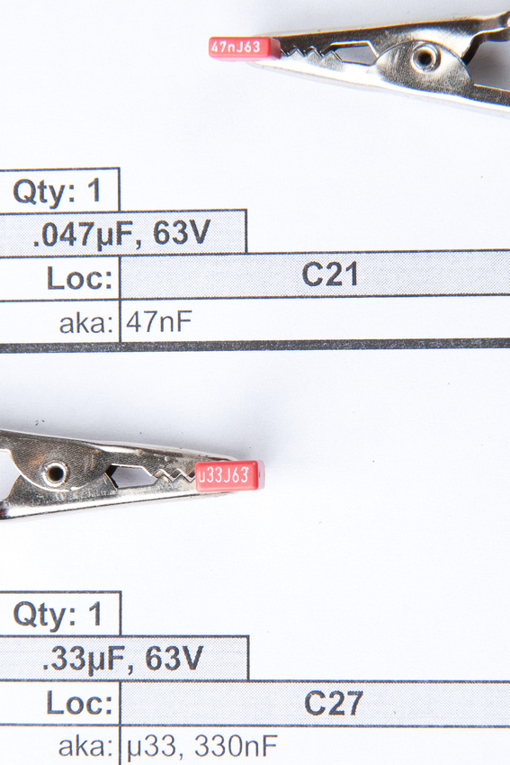
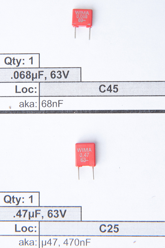
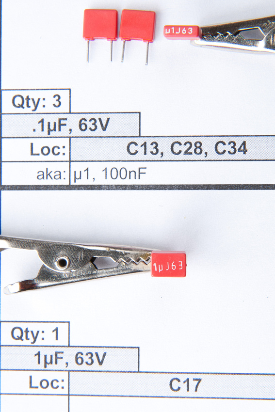
Due to possible confusion on the various labeling conventions on these capacitors, I'm including pictures of the markings.  I ended up having C21 (.047uf) and C25 (.47uf) mixed up on the first pass, so please double check!

p510025661-5.jpg


p127575224-5.jpg


p200126287-5.jpg


p510486758-5.jpg


p369450793-5.jpg


p848197935-5.jpg


p905915855-5.jpg


p865829709-5.jpg
 
Having sorted the film capacitors, it's time to stuff them into the PCB.  On this point, I think there are better ways of doing things, as I'm not 100% happy with how straight my caps ended up lining up on the PCB, but for what it's worth, here's how I did it.

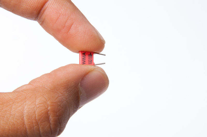
First, I bent the legs of the caps a little.

p204670007-4.jpg


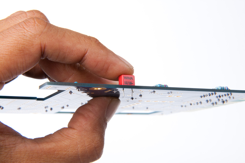
Then, I inserted into the PCB and soldered 1 leg (I can seldom get the caps to seat firmly against the PCB by bending the legs).

p203006558-4.jpg


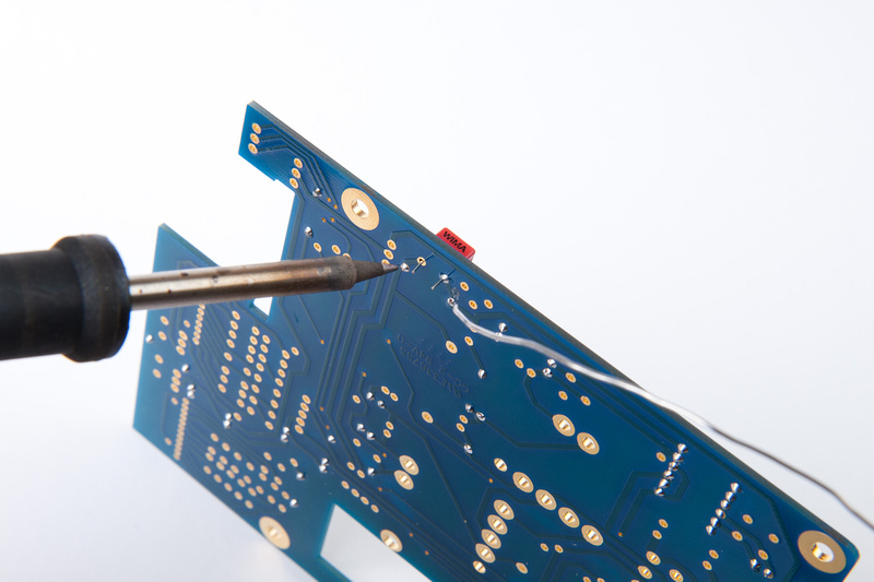
Then, with the PCB on it's side, I solder 1 leg of the film cap.

p363265845-4.jpg


(note: no picture of the next steps because i couldn't figure out how to do it without hurting myself or breaking something).

Next, I re-heat the 1 soldered leg while applying pressure to the cap with my finger seating the cap. . . then, with the cap secured in position, I flip over and solder the 2nd leg.

At any rate, here is the board populated with the film caps. (not as straight as I'd like, but nothing wrong with it either)

p467996696-4.jpg


p155206835-4.jpg
 
Hey Jeff, trying to troubleshoot my VC528's all set up but not passing noise... would love some help on where to start looking... with the DMM

JD
 
JD, first off, what opamps are you using? They need to be known good. Maybe pull a pair from a preamp or something and we'll go from there. Also make sure the rack slot and associated cabling are trouble free.
 
Back
Top