CA-250 EQ // 3 band Sontec in 500 series format

GroupDIY Audio Forum

Help Support GroupDIY Audio Forum:

This site may earn a commission from merchant affiliate links, including eBay, Amazon, and others.
I received the kits today. I've built over a 100 kits and have already commented but I will again.
Build guide, Part Carts, communication, excellent.
Great quality of parts, P.S.B.s, Faceplates, Knobs, Hardware, Even down to the packing.
Everything arrived in in good condition.
You've done it all like a pro.
 
Fits like a glove. Probabaly one of the best builds I've had the pleasure of doing.

Really need a jig to calibrate these though.
 

Attachments

  • IMG_1437.JPG
    IMG_1437.JPG
    543.1 KB
Great build! Mine are finished, but not calibrated. A couple observations.... I had to file down the notches in the PCB where the gain pots go (the ones where you have to bend the pins). Otherwise they were a little too wide. It would probably have been less messy to do that first.... no big deal though.

Also, I would recommend loosely fitting the bypass switch pcb until the faceplate is on, and you're sure the switch will cleanly engage/disengage .  I found it best to only solder one of the pins on the 6 pin header -- that way it's easier to adjust the position of the switch if needed.  On one of mine, it took a little finagling, but the other was a piece of cake.

A very enjoyable build though, and the mouser BOM (plus digikey) was perfect.

 
mdmitch2 said:
I had to file down the notches in the PCB where the gain pots go (the ones where you have to bend the pins).
You shouldn't have to file the pcb. There's clearance for the blue plastic case of the potentiometer and that's all you need.
Thanks for the comments
 
jrasia said:
Really need a jig to calibrate these though.
Easiest option is a 500 Connector Extender:

http://soundskulptor.com/uk/proddetail.php?prod=XT500KIT

https://www.jlmaudio.com/shop/500-51x-extender-cable-kit.html

http://capi-gear.com/catalog/product_info.php?cPath=87_88&products_id=406

https://groupdiy.com/index.php?topic=52462.0 (Module Extender Kit)

Another option is to build a permanent test jig using the Rackit PCB from Igor :

http://www.ramshacklerecording.com/products/rackit/

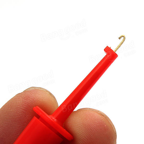
Final option, if you have tiny hook test leads and a Bench Power Supply, you can connect directly to the 12 pin header. The pins are labeled on the PCB.
Be careful not to short the pins. Connect the leads first, then apply power.
9.jpg


Cheers
 
Hi!

One more happy European here!
I just finished my pair yesterday (have to wait for a test jig to calibrate, though). I have to say the build was extremely pleasant! The build guide is really top quality, I'd even say it's on a par with Chunger's legendary photodiaries! Detailed, but not going overboard and showing every single resistor. Extra plus from me for the friendly reminder in step 18 -- It usually takes me at least one molten Wima cap to remember to be careful with the soldering iron in small spaces!  ;D

I also really enjoyed the attention to detail in the design, especially the use of locking nuts, knobs with detents, ease of assembly and so on. :)
The mouser and digikey carts also worked perfectly and for a pair of EQs it was possible to split the order evenly between the two stores to avoid both of the shipping costs (to Europe it's around $20 for orders less than $50).

I agree with mdmitch2 that it might be a good idea not to solder the bypass switch pcb completely before fitting the faceplate for the final time (of course I only thought of this afterwards). The fitting worked out well for me in the end, but having a chance to move the bypass pcb in the final stages would probably make it easier to get the switch to move more freely, as the hole of the switch is a pretty snug fit.

And there's definitely no need to file or modify the pcb.

Thanks again for the extremely nice build! I can't wait to testdrive these!
 

Attachments

  • IMG_5444.jpg
    IMG_5444.jpg
    398.4 KB
Back
Top