Capacitance multiplier: which Darlington to choose?

GroupDIY Audio Forum

Help Support GroupDIY Audio Forum:

This site may earn a commission from merchant affiliate links, including eBay, Amazon, and others.
Highly unlikely to fry a cartridge as the faults common are unlikely to affect inputs.
Better safe than sorry.
Have you ever REALLY tried and compared, as compared to drawing lines on a green table?
No, and I won't. As I said, there are so many things that make phono repro imperfect that I don't really care.
Of course, there are power limits - I'd be unlikely to use such a circuit for a 10kW/2Ohm PA Amp
Neither would I.
I am often bewildered how often old wives tales (e.g. Output Coupling caps in speaker Amp's are bad) are bandied around as fact in (Audio) Electronics, when a rigorous analysis easily falsifies them.
Everything is in the signal path, except the pilot light.
Output caps in power amps have consistantly been underized, designers taking into account only the theoretical -3dB LF point.
In a "standard" amp with +/- rails, the caps are un parallels AC-wise, and the whole amp is under NFB.
With a single rail and an output cap, teh designer has to tahe the output cap under NFB, which many didn't realize as a necessity.
Indeed. These are commonly Bipolar and if they are good quality rather large in size for value/voltage and measure rather well.
Define "quality" and "measure well". :)
As said, I have extensively tested Nichicon ES (THT) & WP (SMD) series bipolars and they have very low distortion, even at low frequencies where they attenuate.
If I still had teh equipment and patience, I would do it.
I can only again recommend Cyril Batemans "Capacitor Sound" series in Wireless World.
Unfortunately, it is outdated, not having followed some of the improvements in capacitor technology since 1983, except for a 2003 complement regarding C0G vs PP.
 
Output caps in power amps have consistantly been underized, designers taking into account only the theoretical -3dB LF point.

Well, maybe they figured that LF power is usually lower than midrange and that distortion perception reduces at LF and thus there is no real problem.

In a "standard" amp with +/- rails, the caps are un parallels AC-wise, and the whole amp is under NFB.

The signal current flows in the capacitors and causes linear and non-linear errors that enter the amplifier via the limited powersupply rejection.

However they are inside the whole amplifiers feedback loop.

With a single rail and an output cap, teh designer has to tahe the output cap under NFB, which many didn't realize as a necessity.

One should consider this as "blindingly obvious, but it appears not so.


Define "quality" and "measure well". :)

Quality = longevity and stability of parameters and sample to sample variations, "measure well" low losses, low ESR &ESL, low harmonic distortion with signals and lack of microphonics.

Unfortunately, it is outdated, not having followed some of the improvements in capacitor technology since 1983, except for a 2003 complement regarding C0G vs PP.

Not quite true, it goes back not to 1983, but 2002, also, i have singularly failed to notice any fundamental improvements in capacitor technology since 2002.

Thor
 
Yes, I use this at times.

In a Phono Preamplifier I do not want input coupling capacitors at cartridge level, IME the negative impact on sound quality is excessive.
I don't believe I have ever heard an "excessive" sound quality deterioration from using a coupling cap in series with a phono input. That said I don't or haven't since the 70s. I have measured errors from a electrolytic cap in series with the gain resistor to ground in the popular non inverting topology. I measured tens of degrees of phase shift at 20kHz... I didn't hear that either, but designed it away in future preamps..
The circuit I showed is really specific to an "All In One active RIAA EQ" Phono stage and perhaps to a direct coupled microphone Preamplifier (yes direct coupled with phantom power).
Wayne made a mic preamp that DC couples the phantom input. Details on his website. (That project actually started on this website but was moved away).
It's application is for situations where the input node is not accessible and serving other nodes is undesirable due to high ac gain from such nodes.


As I use the same Op-Amp type for signal and non-servo, this cannot happen (exceeding slew rate).
I am surely repeating myself but with servos, I worry about high edge rate signals feeding back into an output, or into the signal input. Perhaps I worry too much. 🤔

JR
Blind listening tests tend to let me agree as long as the capacitors Ard not electrochemical types, but film. There even sizing for 4Hz suffices.

Electrochemical capacitors IME must bipolar types to be reliably inaudible at line levels. They exist in values that are usually not sufficient for output coupling capacitors in amplifiers.

If sufficient feedback is applied around electrochemical capacitors, as I showed in my "AC Coupling" case, they become subjectively transparent.

This is generally speaking my preferred solution, wherever applicable combined with using bipolar electrolytic capacitors for coupling (Nichicon ES series measure transparent on AP2).

Thor
 
"measure well" low losses, low ESR &ESL,
All the serious papers conclude there is no corelation between low ESR/ESL an sound quality. I'm not patient enough to have a personal opinion based on experience, though.
Not quite true, it goes back not to 1983, but 2002,
I have found no trace of anything more recent than 1983, except the article that can be found in Linear Audio #12.
Do you have a link?
also, i have singularly failed to notice any fundamental improvements in capacitor technology since 2002.
I have noticed changes, with the loss of PS and PC, the advent of PPS and polymer caps.
In the same package, the electrolytic cap I buy today has twice the capacity and 1.5x the rated voltage of one I bought in 2000.
 
All the serious papers conclude there is no corelation between low ESR/ESL an sound quality. I'm not patient enough to have a personal opinion based on experience, though.
+1... The skunk in the woodpile for audio quality is generally voltage coefficient. Keeping the terminal voltage small keeps the distortion from voltage effects small. In passive loudspeaker crossovers there are concerns about ESR/ESL as it can affect tuning. I already shared the story of me approving a Polypropylene capacitor engineering change inside a passive Peavey crossover last century, because my golden ear's boss wouldn't approve the ($0.20) cost increase.

Esoteric capacitor phenomenon like DA are known for causing errors in sample and hold circuits, in simple audio blocking applications DA is mostly innocuous, while some tried to make a big deal about DA in the audiophool press back in the 80s. .
I have found no trace of anything more recent than 1983, except the article that can be found in Linear Audio #12.
Do you have a link?
I even wrote about capacitors in my Audio Mythology column back in the early 80s.
I have noticed changes, with the loss of PS and PC, the advent of PPS and polymer caps.
In the same package, the electrolytic cap I buy today has twice the capacity and 1.5x the rated voltage of one I bought in 2000.
I have been out of the trenches this century, but the capacitor makers made a number of aggressive improvements in reduced size/volume, dedicated low impedance capacitors for use in switching supplies, and even dedicated audio models (cough) ;) . I am a fan of COG/NPO dielectric and await larger values, while DSP can just about eliminate capacitors entirely.

JR
 
I don't believe I have ever heard an "excessive" sound quality deterioration from using a coupling cap in series with a phono input.

I found gold-plated silver contact relays switching cartridge levels audible as fidelity impairment.

Wayne made a mic preamp that DC couples the phantom input. Details on his website. (That project actually started on this website but was moved away).

I'm familiar with his design. I also made one (unpublished) that is much simpler for similar performance.

I am surely repeating myself but with servos, I worry about high edge rate signals feeding back into an output, or into the signal input. Perhaps I worry too much. 🤔

You worry wrongly.

I am strictly talking about my Citcuit here:

61803-fe84142bbbc4174ab2aa42162527ef2c.png


Here the main gain stage has its input linked to the output via capacitors (RIAA EQ) which would conduct all high edge rate signals to the gain stage inverting input and have the circuits feedback loop oppose such a signal on the output.

Both gain stage and "non-servo" use the same Op-Amp.

If our hypothetical fast edge rate signal (never mind that there is really no source for this hypothetical signal), is injected via a 100 Ohm Resistor into the circuits output (DC compensator input), which has low open loop impedance (emitter/source follower @ ~ 7mA Iq) and even lower closed loop impedance, is sufficiently large and fast to overwhelm the gain stage's feedback loop, then the whole gain stage would be slewing and distorting heavily.

What would enter the "non-servo" would be the residue the main gain stage failed to deal with. I cannot possibly see this as a problem at this point. Anyway, the unity gain AC follower will just pass this faithfully, until it's slewing ability into a 1MOhm load is exceeded, what the main gain stage will be at this point I don't even want to think about.

I seriously fail to comprehend your point, forgive me for saying, this seems not even a strawman you are building, it seems gasping at straws to find something negative.

I suggest you take another close look and analyse the circuit comprehensively.

 Thor
 
All the serious papers conclude there is no corelation between low ESR/ESL an sound quality.

In the speaker crossovers you mentioned, I doubt that. In fact, I'd suggest that ESR is the most audible factor there.

I have found no trace of anything more recent than 1983, except the article that can be found in Linear Audio #12.

The entire article series I talk about was published in the UK print publication "Wireless World" over several issues in 2002/03. An update in linear audio was published in Linear Audio #12 in 2017, also a print publication.

I do not have links to paper publications, sorry. There may be electronic copies available, I do not know.

I have noticed changes, with the loss of PS and PC, the advent of PPS and polymer caps.

PS remains available. PC for audio was always a bit of a curates egg. Polymer Caps have been available in 2002 and in fact were included in CB's tests.

Film capacitors with newer dielectrics were also covered in CB's articles, though perhaps not every precise formulation of what often is called "acrylic" which IME is an excellent replacement for PC, including sonic character.

In the same package, the electrolytic cap I buy today has twice the capacity and 1.5x the rated voltage of one I bought in 2000.

Yes and no. The modern parts often have higher ESR, worse ripple current etc.

High quality Audio parts are typically larger than these modern parts and perform better, objectively.

The biggest advances have actually been in SMD film and ceramic capacitors (size etc), but again, these are mostly not in parts suitable for the analogue audio signal path, but are highly suited to DC-DC conversion, digital power supply decoupling etc.

Thor
 
Esoteric capacitor phenomenon like DA are known for causing errors in sample and hold circuits, in simple audio blocking applications DA is mostly innocuous,

It is not. Again, I recommend Cyril Bateman's article series.

I have been out of the trenches this century, but the capacitor makers made a number of aggressive improvements in reduced size/volume,

Often making the audio related performance worse.

dedicated low impedance capacitors for use in switching supplies,

Yes, especially multilayer ceramic.

and even dedicated audio models (cough) ;)

These most often are actually models that preserve older, larger size designs than now common in commodity electronics that offer objectively better performance.

I am a fan of COG/NPO dielectric and await larger values, while DSP can just about eliminate capacitors entirely.

You still need them in the power supplies.

What I am working on now are completely digital systems, that retain the signal in the digital domain from source to voice coil.

Including multiple layers of DSP, naturally with DSP crossovers, DSP EQ, DSP Dynamics etc. Such systems offer degrees of design freedom and flexibility that is near impossible in analogue.

Thor
 
I found gold-plated silver contact relays switching cartridge levels audible as fidelity impairment.
clicks?
I'm familiar with his design. I also made one (unpublished) that is much simpler for similar performance.
I scratched out multiple variants but never melted solder, as the benefit was more hypothetical than practical (objective). It would take too much effort to educate customers about the benefit and I had no good answer for "so what?".

Another approach I did not pursue was to fly an A/D convertor up to phantom voltage and optically voltage shift down in the digital domain to nominal supply voltages.
You worry wrongly.
I learned to "baby" op amps back in the 70s designing BBD delay lines. Typical op amps back then were pretty poor at absorbing digital clocking glitches in the sampled BBD outputs. I found that using a real pole before any active LPF stages kept them well behaved. I'd rather over design something than under design it, a discipline learned the hard way from mass production.
I am strictly talking about my Citcuit here:

View attachment 109982


Here the main gain stage has its input linked to the output via capacitors (RIAA EQ) which would conduct all high edge rate signals to the gain stage inverting input and have the circuits feedback loop oppose such a signal on the output.

Both gain stage and "non-servo" use the same Op-Amp.

If our hypothetical fast edge rate signal (never mind that there is really no source for this hypothetical signal), is injected via a 100 Ohm Resistor into the circuits output (DC compensator input), which has low open loop impedance (emitter/source follower @ ~ 7mA Iq) and even lower closed loop impedance, is sufficiently large and fast to overwhelm the gain stage's feedback loop, then the whole gain stage would be slewing and distorting heavily.

What would enter the "non-servo" would be the residue the main gain stage failed to deal with. I cannot possibly see this as a problem at this point. Anyway, the unity gain AC follower will just pass this faithfully, until it's slewing ability into a 1MOhm load is exceeded, what the main gain stage will be at this point I don't even want to think about.

I seriously fail to comprehend your point, forgive me for saying, this seems not even a strawman you are building, it seems gasping at straws to find something negative.

I suggest you take another close look and analyse the circuit comprehensively.

 Thor
I am not talking about your design. I am making a general observation about servos in general.

carry on, don't change for me. ;)

JR
 
There are at least two connectors between the cartridge and the preamp in most cases (not counting the solder joints and the connection between lead and chip). Do they also result in fidelity impairment?

Having compared soldered connections to cartridge pins and using non-standard connectors with high connection integrity on phono inputs, in my experience yes.

Would I recommend doing that generally, not particularly.

Thor
 

No, when static.

I scratched out multiple variants but never melted solder, as the benefit was more hypothetical than practical (objective). It would take too much effort to educate customers about the benefit and I had no good answer for "so what?".

There is that. I always found this amusing:

The 48 Volt Phantom Menace Returns – THAT Corporation

Seeing all this cludge should be motivation enough.

Another approach I did not pursue was to fly an A/D convertor up to phantom voltage and optically voltage shift down in the digital domain to nominal supply voltages.

Why so much Rube Goldbergian effort?

Existing circuits, e.g. Cohen with discrete inputs etc. are easily modified to "flying" inputs, with performance gains to boot.

I learned to "baby" op amps back in the 70s designing BBD delay lines. Typical op amps back then were pretty poor at absorbing digital clocking glitches in the sampled BBD outputs. I found that using a real pole before any active LPF stages kept them well behaved.

I do the same thing for Delta/Sigma DAC's, usually using a circuit that combines differential and common mode filtering.

DAC's can output the kind of (parasitic) signals you mentioned.

I'd rather over design something than under design it, a discipline learned the hard way from mass production.

By all means, I'm not Muntz, however appropriate technology applies and that comes from appropriate requirements.

I am not talking about your design. I am making a general observation about servos in general.

My observation about servo's in general is that that it is often best to avoid them all together and if used, they must be designed in with a lot of care.

Mind you, I'd say the same about power supplies and almost everything.

The concept of Lego like copy/pasta generic circuit blobs together (puns intended) to make a high quality product is not realistic.

Either we need the most ridiculously over engineered functional generic blocks which impacts cost, size, weight, complexity (the "Superregulator" is an example) to merely equal "appropriate technology", or we end up worse.

Carry on, don't change for me. ;)

Keep-calm-carry-on-series.jpg

Thor
 
What about this regulator? I think the good results are because the mosfet has a high gfs of 40 -70S.
It is now going to be discontinued and I have built one with IXFP56N30X3 but blew the two I had up. Stupidly left out the protection zener. Then I used the IXFP72N30X3M and its working.
 

Attachments

  • mos no FB reg.gif
    mos no FB reg.gif
    227.6 KB · Views: 1
Thor,
many thanks for sharing your circuit knowledge here.
Got some IRF830 now and want to try your circuit and how it will sound.

For the value of C1 you have choosen a 0.1uF, is this such a small value because the MOSFET has such high gain factor?
Ken san had choosen 22uF which will be multiplied by the circuit. Maybe because his cap multiplier doesn't achieve such high gains like a MOSFET? Could this be a valid indicator for such an assumption? Will the circuit be able to work stable with that bigger cap value, too? Sorry, I don't have experience in simulations and no expensive audio analyzer here for testing.
 

Attachments

  • Masseto.jpg
    Masseto.jpg
    3.6 MB · Views: 0
All other things being equal, the bigger the cap on the gate, the slower the charge/ramp time for the output, but the lower the ripple present on the gate.
 
For the value of C1 you have choosen a 0.1uF, is this such a small value because the MOSFET has such high gain factor?

The Mosfet has nearly infinite input impedance and almost no DC current in the gate, unlike Bipolars.

I remarked elsewhere that the view "effective capacitance is base capacitor times beta" is completely incorrect.

As the capacitances in the Mosfet are small and at low frequencies there is no loading from the Mosfet, we can use a low value capacitor with a high value resistor.

We can use a high quality film capacitor at a very low cost.

The filtering of noise is actually down to 159115/(R*C) (output Hz, R Ohm, C uF) determining the -3dB Point where the RC circuit rolls off noise from the input at 20dB per decade.

The relative input impedance of the active element appears in parallel with the Series resistor of our RC circuit and unless infinity infinity will raise the -3dB Point and reduce filtering.

With the Mosfet being near enough to infinity to not matter 6,800,000 Ohm & 0.1uF we get 0.23 Hz -3dB, -20dB at 2.3Hz, -40dB at 23Hz, -46dB at 46Hz and -52dB at 92 Hz which is close enough to 100/120Hz for government work.

If we use a BJT in the circuit the base impedance is the load impedance on the emitter appx. multiplied with the Beta. So the impedance in parallel with the base capacitor is low and frequency dependent.

Ken san had choosen 22uF which will be multiplied by the circuit.

Shindo San uses BJT. It works sufficiently different.

Will the circuit be able to work stable with that bigger cap value, too?

Yes, but adjust the resistor to match.

The rise time is kind of the inverse of the cutoff frequency, so the larger R * C the slower the voltage rise.

With 6M8 & 0.1uF we have 680mS rise time to 70%. Increase the capacitor to 1uF, the rise time will be 6.8 seconds and the noise will be reduced an additional 20dB over the above values.

There is an eventual "bottom" to noise reduction, depending on circuit and device parasitics, where it flattens out and with real capacitors noise rejection will reach a maximum at a specific frequency of usually 10's of kHz and then get worse again.

Thor
 
I remarked elsewhere that the view "effective capacitance is base capacitor times beta" is completely incorrect.
It's interesting as I see this representation repeated in at least two different text books.

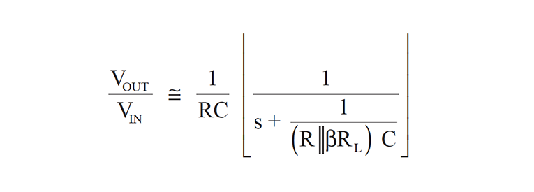
The overall filter response at 'low' frequencies (e.g. before the zero dominates the response) is:
20210217123402_Equation8-BillReeve-CapacitanceMultiplier.png

So whereas a normal RC filter places R in series with the output load, in the multiplier circuit, the beta*C in the denominator also reduces the load resistance by beta as well. In other words, insertion loss from the series R is reduced by a factor of beta.

The reduced low-frequency insertion loss is equivalent to dividing the filter resistance (R) by β, and the lower pole frequency is equivalent to simultaneously multiplying the capacitance (C) by β and dividing the filter resistance (R) by β.

This analysis appears correct, yet you say it's not correct, so I'm curious where the difference lies.
 
The Mosfet has nearly infinite input impedance and almost no DC current in the gate, unlike Bipolars.

If we use a BJT in the circuit the base impedance is the load impedance on the emitter appx. multiplied with the Beta. So the impedance in parallel with the base capacitor is low and frequency dependent.

Shindo San uses BJT. It works sufficiently different.

Thor
Thank you very much, Thor and all participants, for explaining circuit design and working on this task.

I have to admit, this project is not about a budget. Therefore, the PSU has to sound quite good at first. And it has to have sufficient good measurements. I'll try the MOSFET solution, the BJT and they have to compete with a fully tube regulated supply. So they better sound good, or they will never be applied.

I'll be back with an subjective answer for sure.
 
Last edited:
So whereas a normal RC filter places R in series with the output load, in the multiplier circuit, the beta*C in the denominator also reduces the load resistance by beta as well. In other words, insertion loss from the series R is reduced by a factor of beta.

Yes, this view makes some sense. But it is in my view backwards.

What we have is an RC filter followed by an active device (Tube, BJT, FET)

Let us assume an "ideal" transistor with Beta = infinity. This more or less is the case with a real MOSFET, it's gate curent is essentially zero.

Does that mean our capacitor is multiplied by infinity and is now "infinity"? Of course not. Infinite beta simply makes the output "perfectly" follow the RC filters output.

Meanwhile the DC and to a large degree AC output impedance is dominated not beta, but by transconductance which for a BJT is Collector Current in mA / 26. For most bipolar transistors beta shows small variations with collector current, the Transconductance is however shows linear variation with collector current.

Beta and other parasitics comes into play as additional term that "loads down" the RC filter and alters the lowpass response of the filter.

For BJT'S the input impedance arguably reflects the load impedance and if Zin / Beta is large relative to the Transconductance determined emitter impedance, it will dominate.

To check, we assume 52mA load current and thus 2A/V Transconductance or 0.5Ohm output impedance.

Beta is 160 and Cbase is 22uF. Thus at 100Hz & 52mA the emitter impedance is 0.5 Ohm + (72Ohm /160) = 0.95 Ohm.

At 5.2 mA however it will 5.45 Ohm and 520 mA it will be 0.5 Ohm.

Thus "capacitance times beta" is an excessive oversimplification, which is not really useful. The dominant effect is Transconductance (for all devices, Tube, BJT and MOSFET).

Your textbook example omits the Transconductance effects and this does not allow correct analysis of the circuit for both DC and AC.

Why this is, good question. Textbooks often are revised from much older versions that is not completely correct but was carried forward because the circuit is largely out of use and nobody ever updated the text.

The view of beta being dominant in this to be able to ignore transconductance requires a mix of very low beta and rather high and fairly constant load currents, perhaps this assumption was made silently and never enunciated.

Any which way, capacitance times beta is not a valid or useful simplification of analysing the circuit.

This analysis appears correct,

Why would you say that the analysis appears correct? Have you either simulated the circuit or build and measured the circuit and compared results to the textbook analysis? Otherwise I have doubts that you can make such a statement.

Thor
 
Back
Top