Capacitance multiplier: which Darlington to choose?

GroupDIY Audio Forum

Help Support GroupDIY Audio Forum:

This site may earn a commission from merchant affiliate links, including eBay, Amazon, and others.
I noticed you're a big fan of Sziklai.

In many applications it is a better choice than classic darlington for similar parts count.

Note, "many" but not "all".

A Sziklai with J-Fet / Mosfet front stage and BJT back stage is possible, just as we can have a bipolar front stage and mosfet back stage (or J-Fet+ Mosfet) which extends it's usefulness even more.

Darlington and folded darlington (aka Diamond) are also very useful in specific applications.

Thor
 
Pretty standard Op-Amp + Pass Transistor regulator. Easily better than 78XX.
IMO not all that standard..... I liked the way the op amps (072) used in my regulator were powered by the clean already regulated PS rails for extremely good PSRR. PS output noise was down in uV levels.

Details here:

Preserving the "El-Cheapo" DIY Phono Preamp Documentation

I consider this design extremely basic, a "minimum level" design. MM & MC the powersupply is/pre-regulated by a switching regulator which is not shown that creates +/- 12...15V from 5V (USB power) and switches at 1.2MHz, with extra LC filtering to get rid of the 1.2MHz. Audioband noise from this switching regulator is comparable to LM317 optimally applied.

The Actual final PSU Filter/Regulator uses Sziklai Pairs that give a few 100mOhm output impedance with extremely low noise due to the use of low noise transistors.

Thor
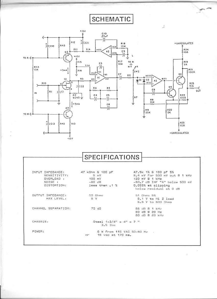
I like the emitter follower biased on class A with a JFET better than my output stage buffers. That front end while open loop would require a very clean PS. I used a JFET front end (MM only), while my current sources to increase current density needed to be clean.
P100.gif

sorry to feed the phono preamp veer...

JR
 
Gents,

having drawn a "Shindo like" tube pre PSU, I wonder wether this circuit can supply high B+ voltages with a

Signal to Noise Ratio of 120 dB ?

I don't see any more regulators in his amps. Formerly he used a fairly simple 6BM8 regulator plus cap multiplier, but that is absent since ages. Wouldn't this combination lead to a better PSRR and more benefits compared to using cap multiplier filters only ?

Personally I think about using an oversized (100mA) tube regulator with the Siemens E235L tube for input and driver stages (approx. 27mA) and a cap multiplier just for the tube output stages (38mA).

Or will the use of one or two cap multipliers (one per channel maybe) still be enough for achiving a good signal to noise ratio and the tube regulator absence won't matter?

IMG_20230608_152134.jpg
 
Last edited:
IMO not all that standard..... I liked the way the op amps (072) used in my regulator were powered by the clean already regulated PS rails for extremely good PSRR. PS output noise was down in uV levels.

I have an old Marantz Amp that has the almost identical same circuit, using NJM2068 for even lower noise, made 1989.

I like the emitter follower biased on class A with a JFET better than my output stage buffers.

I thought that the DC Servo I rolled into this and the "elliptic" rumble filter are much more interesting. And my way of integrating an inverting MC Pre-Pre so it's inversion is cancelled.

That front end while open loop would require a very clean PS.

The open loop frontend is MC only and it has a very clean PSU.

As mentioned, the raw +/- Rails have appx. LM317 levels of noise (and being a 1.2MHz Switcher there is no PSU noise and these rails are then filtered further by dual cascaded capacitance multipliers.

Each Capacitance Multiplier knocks out at least 30dB at LF, more as frequency rises, so from a ~ 30uV 20Hz-20kHz noise level in the unfiltered supply we get to 0.3uV at the Op-Amp's supply pins and 0.01uV (10nV) at the MC Pre-Pre stage power input.

Finally, the capacitors on the Emitters of the open loop MC Pre-Pre together with the bias resistors from a lowpass with a 30mHz turnover, so our 10nV are further reduced into what my iChing calculator reports as "suffusion of imperial yellow" or in plain robust anglo-saxon "a tiny fraction of feck all".

I used a JFET front end (MM only), while my current sources to increase current density needed to be clean.

Yes, I use a FET input Op-Amp with sufficiently low noise (OPA1679) for MM. The BJT's are used for MC

sorry to feed the phono preamp veer...

Well, it has parallel applications in Pro Audio. Microphone Preamp's anyone?

Thor

PS, a commercial Phonostage based largely on this circuit looks like this (warning, naked HiFi porn):

1686233436489.png
1686233451678.png

Mandatory rave review in stereophile here:

The Even More Amazing ifi Micro iPhono 2 MM/MC Phono Preamplifier
 
Gents,

having drawn a "Shindo like" tube pre PSU, I wonder wether this circuit can supply high B+ voltages with a

Signal to Noise Ratio of 120 dB ?

View attachment 109891

Maybe, it would have to be modelled. Do put in a 12V Zener diode from Gate to Source and a 1k Gate Stopper, or at least a 100R/100Mhz ferrite bead. But it seems possible. Necessary? Depends.

Personally I think about using an oversized (100mA) tube regulator with the Siemens E235L tube for input and driver stages (approx. 27mA) and a cap multiplier just for the tube output stage (38mA).

Input & Driver stages need low noise. Output stage is always less critical.

Or will the use of one or two cap multipliers (one per channel maybe) be still enough for achiving a good signal to noise ratio and the tube regulator absence won't matter?

I think so. If you my circuit from post#8 verbatim, you get 70dB for 100Hz noise reduction.
with 66mA I estimate 9V Peak-Peak ripple at the 50uF capacitor.

For that I'd recommend adjusting the resistors so that at least 20V are across the Mosfet.

So after a first stage of Capacitor multiplier 9V P-P will be reduced to 3mV P-P.

If the output stage can handle ~ 1mV RMS rail noise while producing sufficient SNR, this is all that is needed.

If we cascade two Capacitor multipliers, 3mV P-P will be reduced to 1uV P-P or around 0.3uV RMS.

That is low enough to count as extremely low noise.

Btw, is Audio Note using IC regulated PSU in their preamps or cap multipliers?

AFAIK (things may also have changes since Kondo's understudy took over), strictly LCRC or just RCRC, generally with relatively large capacitance...

As seen here in the M7 Preamp:

1686234465135.png

And Neiro 2A3 PSE Amplifier:

1686235046481.png

Thor
 
I have an old Marantz Amp that has the almost identical same circuit, using NJM2068 for even lower noise, made 1989.
I didn't time travel into the future to copy them...
I thought that the DC Servo I rolled into this and the "elliptic" rumble filter are much more interesting. And my way of integrating an inverting MC Pre-Pre so it's inversion is cancelled.
I used a DC servo in my P100.. the servo feedback was introduced into the upper current source.
The open loop frontend is MC only and it has a very clean PSU.
My earlier P10 had a MC version with higher gain and using very low noise bipolar transistors, the MM version of the p-10 used JFET input devices. The P-10 front end was balanced "Cohen" topology, but I didn't know it was called Cohen back then.
As mentioned, the raw +/- Rails have appx. LM317 levels of noise (and being a 1.2MHz Switcher there is no PSU noise and these rails are then filtered further by dual cascaded capacitance multipliers.
I didn't measure my P100 supply noise but estimate it to be in the 10uV ballpark.
Each Capacitance Multiplier knocks out at least 30dB at LF, more as frequency rises, so from a ~ 30uV 20Hz-20kHz noise level in the unfiltered supply we get to 0.3uV at the Op-Amp's supply pins and 0.01uV (10nV) at the MC Pre-Pre stage power input.

Finally, the capacitors on the Emitters of the open loop MC Pre-Pre together with the bias resistors from a lowpass with a 30mHz turnover, so our 10nV are further reduced into what my iChing calculator reports as "suffusion of imperial yellow" or in plain robust anglo-saxon "a tiny fraction of feck all".

Yes, I use a FET input Op-Amp with sufficiently low noise (OPA1679) for MM. The BJT's are used for MC
yes, modern op amps made the whole esoteric phono preamp chase academic...
Well, it has parallel applications in Pro Audio. Microphone Preamp's anyone?
Back in the 70s I discovered the very low noise Rohm 2sb737/2sd786 bipolar devices (now obsolete). They were designed for MC amps but made nice low noise mic preamps (using Cohen topology, etc).
Thor

PS, a commercial Phonostage based largely on this circuit looks like this (warning, naked HiFi porn):

View attachment 109892
View attachment 109893

Mandatory rave review in stereophile here:

The Even More Amazing ifi Micro iPhono 2 MM/MC Phono Preamplifier
here is a piece of a stereophile review of my P100 that ran in the early 1980s. IIRC Larry Greenhill compared it favorably to the several thousand dollar Mark Levinson. I have the full review somewhere. I didn't send my preamp to them for review, I shared it with a different friend who sent it to them without my knowledge. By then I had already given up on the audiophool market so instead I used the proposed IEC 30Hz HPF pole. The RIAA afaik never budged from their response spec for 20Hz gain, and never mentioned a peep about infra sonic response below 20 Hz. IMO the IEC 30Hz proposal was sensible but incompatible with typical RIAA approaches.

JR
 
I used a DC servo in my P100.. the servo feedback was introduced into the upper current source.

Yes. Compare to how I did it:

1686242989217.png

In effect the servo is an AC follower that drives the resistor that forms the 3180uS / 50Hz Zero, but has near infinite (> 120dB) amplification for DC that is ultimately injected via this resistor into the inverting Op-Amp input.

You could remove the servo completely and simply connect the resistor to the servo input, of course now there is DC offset.

As the Op-Amp is the same as the actual gain circuit, but unity gain for AC and with extra low distortion capacitor closing the loop it is in effect transparent and only enters the signal-path fully at 50Hz and below, above 50Hz the influence of the servo is attenuated with the RIAA EQ.

Compare to that any servo that is full-range in the signal path.

Back in the 70s I discovered the very low noise Rohm 2sb737/2sd786 bipolar devices (now obsolete). They were designed for MC amps but made nice low noise mic preamps (using Cohen topology, etc).

2N4401/4403 remain available and are not that much more noisy.

By then I had already given up on the audiophool market so instead I used the proposed IEC 30Hz HPF pole. The RIAA afaik never budged from their response spec for 20Hz gain, and never mentioned a peep about infra sonic response below 20 Hz. IMO the IEC 30Hz proposal was sensible but incompatible with typical RIAA approaches.

The IEC proposal was actually a 16Hz Pole.

My solution is different, a pole at a much lower frequency (~ 8Hz @ 10kLoad which is fine for HiFi, though notbfor pro-audio) but blend the low frequencies below 32Hz to Mono.

The main component in cartridge output that is VLF is out of phase between L/R and the cutter blends LF to mono at 80Hz or higher anyway (Neumann Elliptic filter).

So nothing, except the record warp VLF noise is lost.

Thor
 
Last edited:
Yes. Compare to how I did it:

View attachment 109897

In effect the servo is an AC follower that drives the resistor that forms the 3180uS / 50Hz Zero, but has near infinite (> 120dB) amplification for DC that is ultimately injected via this resistor into the inverting Op-Amp input.

You could remove the servo completely and simply connect the resistor to the servo input, of course now there is DC offset.

As the Op-Amp is the same as the actual gain circuit, but unity gain for AC and with extra low distortion capacitor closing the loop it is in effect transparent and only enters the signal-path fully at 50Hz and below, above 50Hz the influence of the servo is attenuated with the RIAA EQ.

Compare to that any servo that is full-range in the signal path.
I prefer to dumb down DC servos so they do not have to handle any high edge rate signals at their inputs or outputs. Your servo input is LPF by the RIAA LPF so unlikely to be stressed by input signals, but the connected output might see some RF coming back in. The servo op amp output bypassed by a feedback capacitor will likewise stiffen up that op amp output. I'm sure it 's fine but I would be inclined to use a proper LPF RC to ground, at the servo input
2N4401/4403 remain available and are not that much more noisy.
Motchenbacher and Fitchen were pretty complementary about the 4403/4401 in the classic "low-noise electronic design" text. They were ok for 1973 when that book was published. I flogged them on my bench until better came along.
The IEC proposal was actually a 16Hz Pole.
7950 uSec was actually -3dB at 20Hz, but the IEC later withdrew their amendment (proposal) so this all academic, or historic.
My solution is different, a pole at a much lower frequency (~ 8Hz @ 10kLoad which is fine for HiFi, though notbfor pro-audio) but blend the low frequencies below 32Hz to Mono.

The main component in cartridge output that is VLF is out of phase between L/R and the cutter blends LF to mono at 80Hz or higher anyway (Neumann Elliptic filter).

So nothing, except the record warp VLF noise is lost.

Thor
There are numerous ways to slay that dragon, I have lost interest.

Back in those days I was also designing companding tape noise reductions, routinely used for transferring vinyl to magnetic tape. Feeding a raw phono preamp output with no HPF treatment into a 2:1 compandor can result in some wild LF content from warped, or non centered records. That compressed LF content did not effectively record to tape, so upon playback the missing LF created a phantom envelope modulation. Not to veer, from a veer, with another a veer.... but I resolved that phantom modulation problem with an adaptive HPF designed into the NR compressor stage. For nominal line level signals the LF cut off extended below 20Hz, but at low levels when the compressor was cranking in tens of dB gain, the LF cut off was scaled up high enough to squash the LF warp artifacts.

JR
 
Your servo input is LPF by the RIAA LPF so unlikely to be stressed by input signals,

Technically, it is not a traditional servo, which is the point. It does however perform the function.

but the connected output might see some RF coming back in.

Doubtful.

The servo op amp output bypassed by a feedback capacitor will likewise stiffen up that op amp output.

??? Without the 100n/22M it would just be a simple follower.

I'm sure it 's fine but I would be inclined to use a proper LPF RC to ground, at the servo input

That would not work. It must replicate the main output, to ensure the AC feedback loop of the RIAA EQ is closed correctly.

Motchenbacher and Fitchen were pretty complementary about the 4403/4401 in the classic "low-noise electronic design" text. They were ok for 1973 when that book was published. I flogged them on my bench until better came along.

Right now most "better" parts have disappeared again, the old warhorses soldier on.

Back in those days I was also designing companding tape noise reductions, routinely used for transferring vinyl to magnetic tape.

Ohh, companders. East Germany was working on a compander for LP (aka UC - Universal Compander), quite interesting. It also had ways to deal with this. plus tick's & pops.

Mind you, to record LP to Tape (unless K7) should not require noise reduction. LP is so noisy.

Thor
 
Disregard, I am not suggesting changes to your preamp design...

I am not changing it, it is objectively and subjectively extremely successful.

I was trying to make you understand mt "not a servo" DC offset correction in my Phono.

Your servo is differential and thus needs tightly matched capacitors and resistors and is followed by lowpass using electrolytic capacitors and then modulates a current source that feeds the second-most sensitive node in the circuit. Thus to you any "AC" is an error signal.

This has always been my problem with servo's. Any AC is an "error" and the circuit amplifies capacitor imperfections compared to a simple coupling capacitor.

As a result, for a long time I used coupling capacitors instead and enclose them in feedback loops (actually, I still do most often). I found the result objectively and subjectively preferable to Servo's.

I concluded, that if AC in the Servo is a problem we try to eradicate and fail to, why not turn the problem from it's head onto it's feet and accept that we cannot avoid AC in the servo.

So instead I decided to make an auxiliary DC correction circuit that is deliberately part of the AC signal circuit and is made transparent relative to the signal path and performs the DC zero function as well.

Allow me to illustrate:

1686296310275.png
Thor
 
I prefer the "classic servo coupled" example for reasons I have already shared. I have seen any number of DC servos that were not protected from high edge rate signals (input or output).

Don't change for me... ;)

JR
 
Allow me to illustrate:

View attachment 109921
Thor
Here's another possibility, which doesn't require matching around the servo opamp.
servo output option.jpg

And yet another, which dispenses with the input cap and solves the issue of signals exceeding the servo opamp's slew-rate.
servo output option2.jpg
As often, many ways to skin a cat.

Personally, I've never used servo outputs. This habit comes from a time where the best amps passed DC (Drown DC300A). I've always used oversized capacitors. Sizing them for 0.02Hz @-3dB ensures the voltage across them is low enough to make distortion negligible.
 
I guess I could do the analysis myself, but with a BJT, beta is used as the multiplication factor for capacitance (in other words, the capacitance on the base is multiplied by beta). What is the analogous multiplication factor for a MOSFET in the same spot?
 
Here's another possibility, which doesn't require matching around the servo opamp.
View attachment 109943

Yes, I use this at times.

In a Phono Preamplifier I do not want input coupling capacitors at cartridge level, IME the negative impact on sound quality is excessive.

The circuit I showed is really specific to an "All In One active RIAA EQ" Phono stage and perhaps to a direct coupled microphone Preamplifier (yes direct coupled with phantom power).

It's application is for situations where the input node is not accessible and serving other nodes is undesirable due to high ac gain from such nodes.

And yet another, which dispenses with the input cap and solves the issue of signals exceeding the servo opamp's slew-rate.
View attachment 109946

As I use the same Op-Amp type for signal and non-servo, this cannot happen (exceeding slew rate).

Personally, I've never used servo outputs. This habit comes from a time where the best amps passed DC (Drown DC300A). I've always used oversized capacitors. Sizing them for 0.02Hz @-3dB ensures the voltage across them is low enough to make distortion negligible.

Blind listening tests tend to let me agree as long as the capacitors Ard not electrochemical types, but film. There even sizing for 4Hz suffices.

Electrochemical capacitors IME must bipolar types to be reliably inaudible at line levels. They exist in values that are usually not sufficient for output coupling capacitors in amplifiers.

If sufficient feedback is applied around electrochemical capacitors, as I showed in my "AC Coupling" case, they become subjectively transparent.

This is generally speaking my preferred solution, wherever applicable combined with using bipolar electrolytic capacitors for coupling (Nichicon ES series measure transparent on AP2).

Thor
 
Last edited:
I guess I could do the analysis myself, but with a BJT, beta is used as the multiplication factor for capacitance (in other words, the capacitance on the base is multiplied by beta).

Nope, it is not. Not really.

In most applications the view of the transistor as current amplifier is unhelpful.

In this circuit we operate grounded collector/drained/anode (aka follower).

There is no "multiplication factor" for the capacitance at the base/gate/grid.

The AC behavior is dominated by Transconductance for all devices, be they BJT, MOSFET or Tube.

The voltage at the input terminal (base/gate/grid) is replicated at the output terminal limited by the Transconductance which in turn is responsible for the apparent output impedance (plus external resistances).

So ripple rejection is down to the RC filter effect of the RC filter to the input terminal, INCLUDING THE EFFECT OF PARASITICS.

I prefer to view the BJT as a voltage controlled current source with a certain degree of internal feedback lowering it's collector impedance (in essence the same way as I view Mosfet's and Tubes) and with a non-linear parasitic resistor between Base & Emitter (like a Tube in Class A/BA/B2 with the grid positive).

It works very well even if the transistor operates in current driven conditions, which is exceedingly rare in real circuits, as pure base current driven transistor circuits do not work that well (exceptions apply).

Thor
 
Last edited:
In a Phono Preamplifier I do not want input coupling capacitors at cartridge level,
I'd rather have whatever imperfections due to a capacitor in the input than a fried cartridge caused by a defective circuit. I can fix almost any phono preamp, but I can't fix a fried cartridge.
IME the negative impact on sound quality is excessive.
IMO the whole process of mechanical reproduction is so fraught with imperfections, I can stand the iota that comes from an input cap operating at a few millivolts and nanoamps.
Ard not electrochemical types, but film.
There even sizing for 4Hz suffices.
4uf film caps are excessively bulky in many cases.
Electrochemical capacitors IME must bipolar types to be reliably inaudible at line levels. They exist in values that are usually not sufficient for output coupling capacitors in amplifiers.
Do you mean between amp and speaker? That is definitely not good practice. Some do not hesitate to use electros in passive x-overs, though... :(
 
I'd rather have whatever imperfections due to a capacitor in the input than a fried cartridge caused by a defective circuit. I can fix almost any phono preamp, but I can't fix a fried cartridge.

Highly unlikely to fry a cartridge as the faults common are unlikely to affect inputs.

IMO the whole process of mechanical reproduction is so fraught with imperfections, I can stand the iota that comes from an input cap operating at a few millivolts and nanoamps.

Have you ever REALLY tried and compared, as compared to drawing lines on a green table?

4uf film caps are excessively bulky in many cases.

Yup.

Do you mean between amp and speaker? That is definitely not good practice.

Nope, it is not a problem IF the feedback loop is implemented correctly.

A Single Rail, output capacitor coupled Amplifier with the correct feedback loop performs no different than a split rail, "direct coupled" Amplifier (which still has the two power supply capacitors in the signal loop and uses negative feedback to lower the noise and distortion from these capacitors), but is inherently DC fault safe.

Of course, there are power limits - I'd be unlikely to use such a circuit for a 10kW/2Ohm PA Amp, but for a 50-200W Amplifier for passive monitors or for example to drive Midrange/Treble in an active Speaker with a bridged Class D Amp for LF - it's an excellent alternative.

I am often bewildered how often old wives tales (e.g. Output Coupling caps in speaker Amp's are bad) are bandied around as fact in (Audio) Electronics, when a rigorous analysis easily falsifies them.

Some do not hesitate to use electros in passive x-overs, though... :(

Indeed. These are commonly Bipolar and if they are good quality rather large in size for value/voltage and measure rather well.

As said, I have extensively tested Nichicon ES (THT) & WP (SMD) series bipolars and they have very low distortion, even at low frequencies where they attenuate.

I can only again recommend Cyril Batemans "Capacitor Sound" series in Wireless World.

Thor
 

Latest posts

Back
Top