You are using an out of date browser. It may not display this or other websites correctly.
You should upgrade or use an alternative browser.
You should upgrade or use an alternative browser.
Capacitance multiplier: which Darlington to choose?
- Thread starter Walter66
- Start date


Help Support GroupDIY Audio Forum:
This site may earn a commission from merchant affiliate
links, including eBay, Amazon, and others.
thor.zmt
Well-known member
A bit of a veer but that reminds me of something I came up with years ago.
The cheap 78xx/79xx 3 terminal voltage regulators were inexpensive and ubiquitous. They were serviceable but based on modest semiconductor technology internally (similar gain/bandwidth to the 741 op amps). The effective result was a rising output impedance at higher frequencies as the internal circuitry lost gain. Prudent designers added capacitors across the PS rails to stiffen them up at HF. I determined that hanging a 1,000 uF electrolytic capacitor directly across the regulator output extended the low source impedance for another octave or two.
That's been recommended a lot around that time. It needs care to design in, match capacitor ESR to the output impedance of the regulator and select the values correctly.
All common 3-Pin regulators are pretty noisy as well.
A better solution is a nominal small capacitor to ensure stability for the regulator and then a build-out resistor with a power supply capacitor to handle the worst case peak current of the circuit being supplied. It will reduce noise and keeps signal current for higher frequencies out of the rather not so great regulator.
For a line output driving +22dBU into 600 Ohm 1,000uF + 1000uF & 10 Ohm series resistors will work well for any regulator in use that is normally stable in circuit.
With 10R +1,000uF we get a 16Hz lowpass, so at 160Hz PSRR is improved by 20dB and 40dB @ 1.6kHz. As common feedback circuitry has the largest amount of open loop gain and PSRR this circuit is "harmless" where its impedance is high (extra NFB available will compensate) and has low impedance and most noise reduction at higher frequencies where the supplied circuit runs of of available feedback and PSRR.
With the contemporaneous 5532 open loop gain is ~100dB with a 100Hz corner frequency and 20dB/decade gain reduction, the equally commonly found TL072 is similar. Both have PSRR (and CMMR BTW) falling off above a few 100Hz. So the RC filter will help a fair bit.
Caveat: check for stability issues trying this trick with modern regulators and modern electrolytic capacitors.
It can be a serious problem. Adding a build-out resistor or inductor after the regulator is preferred, IME.
Thor
At first, when studying those Shindo designs thirty year ago, my first thought was in the direction of using one of those IC voltage regulators.
But then, I read about their inherent noisy designs. Does this really matter in this application, their purpose is just supressing low frequency ripple.
In which region does the noise contribute to the signal? Is it just high frequency noise?
"The LM741 series are general-purpose operational amplifiers which feature improved performance over industry standards like the LM709"
If they are good for audio signals, they should be good enough for simple ripple rejection, true or wrong?
My Studer 810 uses 40 year old NE5532 and some people on the net do upgrade to better OP. I think it just sounds good as it is.
Can it be that Shindo San thought the same way as a pragmatist, he reduced the standard 6BM8 voltage regulator circuit to a minimum and did this with the cap multiplier circuit, too. 30 years ago, the MOSFET third generation IRF830 was surely not available for him.
But for those voltage regulator IC (78xx, LM317 etc), I think a second transistor for high voltage regulation is needed, too?
Last edited:
I will repeat for the cheap seats this was done several decades ago when typical electrolytic capacitors had higher ESL and ESR, so of course stability is a concern with modern caps. Check your results with modern parts.That's been recommended a lot around that time. It needs care to design in, match capacitor ESR to the output impedance of the regulator and select the values correctly.
All common 3-Pin regulators are pretty noisy as well.
A better solution is a nominal small capacitor to ensure stability for the regulator and then a build-out resistor with a power supply capacitor to handle the worst case peak current of the circuit being supplied. It will reduce noise and keeps signal current for higher frequencies out of the rather not so great regulator.
For a line output driving +22dBU into 600 Ohm 1,000uF + 1000uF & 10 Ohm series resistors will work well for any regulator in use that is normally stable in circuit.
With 10R +1,000uF we get a 16Hz lowpass, so at 160Hz PSRR is improved by 20dB and 40dB @ 1.6kHz. As common feedback circuitry has the largest amount of open loop gain and PSRR this circuit is "harmless" where its impedance is high (extra NFB available will compensate) and has low impedance and most noise reduction at higher frequencies where the supplied circuit runs of of available feedback and PSRR.
With the contemporaneous 5532 open loop gain is ~100dB with a 100Hz corner frequency and 20dB/decade gain reduction, the equally commonly found TL072 is similar. Both have PSRR (and CMMR BTW) falling off above a few 100Hz. So the RC filter will help a fair bit.
It can be a serious problem. Adding a build-out resistor or inductor after the regulator is preferred, IME.
Thor
My original design goal was extending the mOhm source impedance out an octave or two above the audio bandpass, so adding a 10 ohm build out resistance would have defeated that purpose. In hindsight an appropriate inductor would satisfy both goals. I made crude measurements by driving a HF sine wave back into the regulated output through a series resistor and calculating the effective source impedance from voltage divider ratio. I didn't keep this secret and recall a casual mention in passing in the back of an AES journal.
JR
thor.zmt
Well-known member
But then, I read about their inherent noisy designs. Does this really matter in this application, their purpose is just supressing low frequency ripple.
If you follow the IC regulator with a RC filter chain, the noise is pretty immaterial. If you use it to regulate the power supply for a PP Tube Amp the noise will not be material.
So it really, really really depends on the design specificas.
In which region does the noise contribute to the signal? Is it just high frequency noise?
Linear regulators have similar noise behavior as Op-Amp's (technically they are actually Op-Amp's for 99.9% of the analysis), plus the noise from the voltage reference, usually bandgap. This means there will be a sloping noise from DC downwards towards an inflection point usually somewhere between 100Hz and 10kHz where the noise becomes constant with frequency. So the most noise is usually subsonic.

"The LM741 series are general-purpose operational amplifiers which feature improved performance over industry standards like the LM709"
If they are good for audio signals, they should be good enough for simple ripple rejection, true or wrong?
They are NOT good enough for Audio, if you ask me.
My Studer 810 uses 40 year old NE5532 and some people on the net do upgrade to better OP. I think it just sounds good as it is.
NE5532 vs 741 is like V69 vs. the amplifier in an old AM only radio. Or worse.
Can it be that Shindo San thought the same way as a pragmatist, he reduced the standard 6BM8 voltage regulator circuit to a minimum and did this with the cap multiplier circuit, too. 30 years ago, the MOSFET third generation IRF830 was surely not available for him.
The IRF830 was probably available 30 Years ago, but a bit exotic. In Japan it would have been a 2SK... something anyway.
But for those voltage regulator IC (78xx, LM317 etc), I think a second transistor for high voltage regulation is needed, too?
Again, it depends. The cascoding transistor is a must for reliability if it is treated as "generic building block".
Optimising the circuit, just a zener diode across in-out to limit the voltage MAY be enough.
Thor
The 741 was a remarkable achievement (compensation cap integrated onto the IC) for the time, opening up op amp circuit design to even more people. Lots of decent audio passed through 741 and 1458 (dual) op amp audio paths. As long as signal levels were kept modest (like -10dBV). The 1/2V per uSec was not a major problem.If you follow the IC regulator with a RC filter chain, the noise is pretty immaterial. If you use it to regulate the power supply for a PP Tube Amp the noise will not be material.
So it really, really really depends on the design specificas.
Linear regulators have similar noise behavior as Op-Amp's (technically they are actually Op-Amp's for 99.9% of the analysis), plus the noise from the voltage reference, usually bandgap. This means there will be a sloping noise from DC downwards towards an inflection point usually somewhere between 100Hz and 10kHz where the noise becomes constant with frequency. So the most noise is usually subsonic.
View attachment 109863
They are NOT good enough for Audio, if you ask me.
NE5532 vs 741 is like V69 vs. the amplifier in an old AM only radio. Or worse.
The IRF830 was probably available 30 Years ago, but a bit exotic. In Japan it would have been a 2SK... something anyway.
Again, it depends. The cascoding transistor is a must for reliability if it is treated as "generic building block".
Optimising the circuit, just a zener diode across in-out to limit the voltage MAY be enough.
Thor
553x and 07x op amps were the new generation of op amps (1970s so not very new now) that were much better than needed for typical audio crunching. Faster than audio, and low enough noise for most line level or modest noise gain applications. Properly used they are more than good enough to not be the weakest link in a modern audio chain.
The 3 terminal regulator a little like the 741 was an improvement making regulators easier design-in and use. Before the 3 terminal regulators we had to deal with ICs like the ua723 basically an op amp and voltage reference on a single chip. Back in the 60s as a technician I had to work with another early regulator IC (LM100). A clever design engineer from Raytheon tricked the LM100, a basic linear regulator to operate as the brain for a switching power supply (used inside a navy rescue vehicle DC-DC power supply).
Again I apologize for this veer dredging up old obsolete technology (no the 553x/07x are not obsolete yet).
JR


thor.zmt
Well-known member
I will repeat for the cheap seats this was done several decades ago when typical electrolytic capacitors had higher ESL and ESR, so of course stability is a concern with modern caps. Check your results with modern parts.
Check your results with ANY parts. More, you cannot absolutely rely on current 78XX/79XX being the same as old.
My original design goal was extending the mOhm source impedance out an octave or two above the audio bandpass, so adding a 10 ohm build out resistance would have defeated that purpose.
Forgive me being cynical, but what specific result do you expect from the mOhm source impedance? More to the point, a nonlinear one.
In hindsight an appropriate inductor would satisfy both goals.
It will add a bit of DCR.
I made crude measurements by driving a HF sine wave back into the regulated output through a series resistor and calculating the effective source impedance from voltage divider ratio.
Yes. A more extended test would have revealed a few interesting things that made me universally using discrete regulators (Sziklai) with pre-loading of 50% of the expected Idelta and an "open loop" (other than the Sziklai Pair) design in positions where the impedance and AC behaviour/impedance matter.
I didn't keep this secret and recall a casual mention in passing in the back of an AES journal.
Possible. I remember reading about this from Walt Jung in TAA ages ago.
Thor
thor.zmt
Well-known member
The 741 was a remarkable achievement (compensation cap integrated onto the IC) for the time, opening up op amp circuit design to even more people.
Hmmm, I have an article from Harris somewhere where they described in detail the design of a wideband (video) J-Fet input Op-Amp, which would not look out of place next to the latest Audio Parts from TI, in terms of objective performance. It was contemporary with the 741.
The 741 was ok for near DC circuits, like industrial control.
For AC/Audio the uA709 was much better.
The 3 terminal regulator a little like the 741 was an improvement making regulators easier design-in and use. Before the 3 terminal regulators we had to deal with ICs like the ua723 basically an op amp and voltage reference on a single chip.
The uA723 allows a MUCH better DC regulator to be made, all across the board. Objectively, in terms achievable performance, 78XX was a huge step backwards from uA723 in performance terms. Oc course, a brain amputated ejit can use 741 and 78XX, something that cannot be said about uA723 and uA709. Convenience trumped performance.
I did my mixing desk casette designs back in east germany with discrete op-amp's, A709 (East German uA709 copy) and A723 (uA723 copy) because they did much better than 741/78XX.
I also use some Siemens Part copies (TAA761 etc) which were audio specialised parts with an open collector output, ~ 90dB OLG with > 100kHz OLG bandwidth used normally with a resistor to +V, but other options could be applied. Why anyone would want to use 741/1458 for audio when such parts were available at the same time is beyond me.

Again I apologize for this veer dredging up old obsolete technology (no the 553x/07x are not obsolete yet).
5532 and 07X are absolutely obsolete for audio use and have been for a decade or two. Some people like to use obsolete stuff, mind you.
Thor
in fact 78xx/79xx are not the same from different manufacturers. At Peavey I blackballed one major IC manufacturer who refused to guarantee a noise spec for their regulators. They managed 6 sigma quality by making the performance criteria impossible to fail.Check your results with ANY parts. More, you cannot absolutely rely on current 78XX/79XX being the same as old.

Since my designs were already better than I could hear, I pursued better specs because I could inexpensively. The 3 terminal regulators already deliver mOhm performance at low frequency, the simple addition of 1,000 uF capacitors complemented the rising output impedance with the falling capacitor impedance until reaching the capacitor's ESL/ESR impedance minima.Forgive me being cynical, but what specific result do you expect from the mOhm source impedance? More to the point, a nonlinear one.
if I used oneIt will add a bit of DCR.
Good analog path design should not depend on PS design for good performance. Not to veer, from my veer, but I recall that Brad (RIP) was working on some esoteric topology for a preamp design that had poor PSRR, requiring a dedicated very low noise power supply. I don't believe he ever finished that design.Yes. A more extended test would have revealed a few interesting things that made me universally using discrete regulators (Sziklai) with pre-loading of 50% of the expected Idelta and an "open loop" (other than the Sziklai Pair) design in positions where the impedance and AC behaviour/impedance matter.
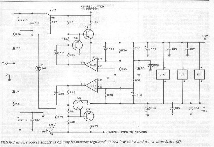
for an example of my power supply design overkill here is the PS from my last phono preamp (to end all phono preamps).
Might have been me... I had a few exchanges with the lads at TAA when they were promoting IMO hyperbolic audiophoolery . I was a TAA advertiser and Ed Dell (RIP) is missed. I tried to get Ed to interview Rudy Bozak before he died. He said he wanted to but didn't get around to doing it before Rudy died. Rudy used to drive up to Hartford Ct with his wife for dinners with me. I proposed that Ed could drive down to Hartford to meet Rudy half way.Possible. I remember reading about this from Walt Jung in TAA ages ago.
Thor
IIRC Harris had a proprietary silicon process that delivered wide bandwidth. Did I mention I am cheap, the harris op amps were not very cheap.Hmmm, I have an article from Harris somewhere where they described in detail the design of a wideband (video) J-Fet input Op-Amp, which would not look out of place next to the latest Audio Parts from TI, in terms of objective performance. It was contemporary with the 741.
I read a article in the IEEE journal about how significant the ua741 design wasThe 741 was ok for near DC circuits, like industrial control.
709s were hand grenades that would fail if you looked at them crosseyed.For AC/Audio the uA709 was much better.
LM301s used with feedforward compensation didn't suck when used inverting.
I repeat 552x and 07x when applied properly are not the weakest link for general audio paths. So there is no reason to swap them out of working designs (unless you have too much time and too much money).The uA723 allows a MUCH better DC regulator to be made, all across the board. Objectively, in terms achievable performance, 78XX was a huge step backwards from uA723 in performance terms. Oc course, a brain amputated ejit can use 741 and 78XX, something that cannot be said about uA723 and uA709. Convenience trumped performance.
I did my mixing desk casette designs back in east germany with discrete op-amp's, A709 (East German uA709 copy) and A723 (uA723 copy) because they did much better than 741/78XX.
I also use some Siemens Part copies (TAA761 etc) which were audio specialised parts with an open collector output, ~ 90dB OLG with > 100kHz OLG bandwidth used normally with a resistor to +V, but other options could be applied. Why anyone would want to use 741/1458 for audio when such parts were available at the same time is beyond me.
View attachment 109868
5532 and 07X are absolutely obsolete for audio use and have been for a decade or two. Some people like to use obsolete stuff, mind you.
Thor
Of course there are newer better parts, how much do you want to spend?
JR
Last edited:
I had a mistake in my first sim; now I've corrected it and I see exactly the opposite of yours. The Darlington beats the MOSFET.I did a Sim with Tina TI, using the build in IRF830 Model and a discrete TIP122 (BC109+BD140-16) for comparison
I would chalk this difference to the validity of the models, which is a recurring issue. Even the most respectable manufacturers sometimes publish crappy SPICE models.
Green is MOSFET, red is BJT.
It just shows that simulation is to be taken with a bucket of salt.

The difference between 6.8Meg/100n and 68k/10uf is negligible in simulation., with the RC at the base scaled to 68k/10uF insted of 6.8M/100n.
thor.zmt
Well-known member
I had a mistake in my first sim; now I've corrected it and I see exactly the opposite of yours. The Darlington beats the MOSFET.
I would chalk this difference to the validity of the models, which is a recurring issue. Even the most respectable manufacturers sometimes publish crappy SPICE models.
MOSFET Models especially are are an issue, you need fairly complex models.
Can you post the model you used?
In reality Mosfet beats Darlington.
Thor
thor.zmt
Well-known member
Good analog path design should not depend on PS design for good performance.
Well, the PSU is the output signal. If NFB is used to correct excessive noise there, it is limited.
for an example of my power supply design overkill here is the PS from my last phono preamp (to end all phono preamps).
Pretty standard Op-Amp + Pass Transistor regulator. Easily better than 78XX.
Here one of mine:

Details here:
Preserving the "El-Cheapo" DIY Phono Preamp Documentation
I consider this design extremely basic, a "minimum level" design. MM & MC the powersupply is/pre-regulated by a switching regulator which is not shown that creates +/- 12...15V from 5V (USB power) and switches at 1.2MHz, with extra LC filtering to get rid of the 1.2MHz. Audioband noise from this switching regulator is comparable to LM317 optimally applied.
The Actual final PSU Filter/Regulator uses Sziklai Pairs that give a few 100mOhm output impedance with extremely low noise due to the use of low noise transistors.
Thor
See attachment.MOSFET Models especially are are an issue, you need fairly complex models.
Can you post the model you used?
As I was wondering why we had so contradictory results, I submitted my sim to the LTspice group, and they confirmed my results (after I had corrected a stupid error).In reality Mosfet beats Darlington.
They used the same model as me. That may be the issue...or not.
Attachments
thor.zmt
Well-known member
The difference between 6.8Meg/100n and 68k/10uf is negligible in simulation.
Not for the DC voltage drop.
Thor
Almost anything is better than 78XX. However they have been and still are used profitably in many designs. In many cases, it's just a matter of not letting this noise penetrate the circuits.Pretty standard Op-Amp + Pass Transistor regulator. Easily better than 78XX.
The worst case is distributed regulators, where the noise current passes through a large loop.
Sometimes I see tinkerers installing crazy expensive regulators that result in no benefit because the layout and decoupling have already taken care of noise current circulation.
In addition, there are products where the circuits have intrinsic good PSRR, where the effect of reducing rail noise is negligible.
thor.zmt
Well-known member
See attachment.
As I was wondering why we had so contradictory results, I submitted my sim to the LTspice group, and they confirmed my results (after I had corrected a stupid error).
They used the same model as me. That may be the issue...or not.
That's a level 1 model, pretty generic and only really suited to logic/switching simulation, not linear operation. My Sim uses a level 3 Model.
Thor
thor.zmt
Well-known member
Almost anything is better than 78XX. However they have been and still are used profitably in many designs. In many cases, it's just a matter of not letting this noise penetrate the circuits.
The worst case is distributed regulators, where the noise current passes through a large loop.
Sometimes I see tinkerers installing crazy expensive regulators that result in no benefit because the layout and decoupling have already taken care of noise current circulation.
In addition, there are products where the circuits have intrinsic good PSRR, where the effect of reducing rail noise is negligible.
There are a few things in electronics few people "get", even degreed engineers and PhD's...
Current flows in loops and like water, will take the path of least resistance.
Voltages in active circuits are created by current flowing in impedances.
Ground is just another signal conductor (I often render it as "Ground Isn't").
There is no such thing as DC in the real world.
"digital" is actually "analog".
Thor
Of course, with the b-e resistors in the Darlington, the base current is much higher. Wthout them, the voltage drop is about 10V for the MOSFET and 15V for the BJT, out of which 5V due to the 100R resistor.Not for the DC voltage drop.
thor.zmt
Well-known member
Of course, with the b-e resistors in the Darlington, the base current is much higher.
Off the shelf Darlington transistors all tend to have them. That is why I included them.
If you make a discrete "darlington" then a so-called "inverted darlington" or Sziklai Pair is a better choice.
Thor
I noticed you're a big fan of Sziklai.If you make a discrete "darlington" then a so-called "inverted darlington" or Sziklai Pair is a better choice.
Similar threads
- Replies
- 2
- Views
- 769
- Replies
- 13
- Views
- 1K