Dimitree
Well-known member
- Joined
- Jul 26, 2011
- Messages
- 125
hi everyone
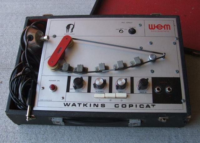
as an experiment, just for fun, I'm trying to build a cheap and simple tape echo.
Something ispired by this, for example:

As a starting point, I took out, from an old and cheap Aiwa hi-fi, the magnetic heads (erase head, record head and playback head) used on the cassette deck and its associated circuit.
I'm not going to use the cassette deck mechanism as it is, I'd like to build my own mechanism, more or less like on the previous example, where tape is not sealed on a cassette and attached to reels, but is a loop in the "open air".
For the moment my concern is not about the mechanical issues (like how to make a tape loop, how to move the loop, align heads, etc), so I'm assuming that these issues were already addressed.
What I'd like to focus on now is understanding how to simplify the electronic circuit used to write/read the magnetic heads.
Since the PCB that houses the original circuit is huge (since on the same board the power amp and the tuner are also present), I would like to re-build the needed section of the circuit, or alternatively build an equivalent circuit.
This is the circuit I'm talking about, with highlighted in yellow the tape section:
http://www.ed-sounds.com/prova1.png
The most obscure parts to me are that BD3881 IC and the fet switching.
I searched for a datasheet of that IC, I only found a really criptic one, and this is the link:
http://pdf1.alldatasheet.com/datasheet-pdf/view/87881/ROHM/BD3881FV.html
Is it something really special, or maybe I could build a simple op-amp equivalent circuit, and avoid the need of that IC?
Also, do I really need to use all those FETs, given the fact that I must continuously/simultaneously write and read?
what's for all that switching?
thank you for the support!
as an experiment, just for fun, I'm trying to build a cheap and simple tape echo.
Something ispired by this, for example:

As a starting point, I took out, from an old and cheap Aiwa hi-fi, the magnetic heads (erase head, record head and playback head) used on the cassette deck and its associated circuit.
I'm not going to use the cassette deck mechanism as it is, I'd like to build my own mechanism, more or less like on the previous example, where tape is not sealed on a cassette and attached to reels, but is a loop in the "open air".
For the moment my concern is not about the mechanical issues (like how to make a tape loop, how to move the loop, align heads, etc), so I'm assuming that these issues were already addressed.
What I'd like to focus on now is understanding how to simplify the electronic circuit used to write/read the magnetic heads.
Since the PCB that houses the original circuit is huge (since on the same board the power amp and the tuner are also present), I would like to re-build the needed section of the circuit, or alternatively build an equivalent circuit.
This is the circuit I'm talking about, with highlighted in yellow the tape section:
http://www.ed-sounds.com/prova1.png
The most obscure parts to me are that BD3881 IC and the fet switching.
I searched for a datasheet of that IC, I only found a really criptic one, and this is the link:
http://pdf1.alldatasheet.com/datasheet-pdf/view/87881/ROHM/BD3881FV.html
Is it something really special, or maybe I could build a simple op-amp equivalent circuit, and avoid the need of that IC?
Also, do I really need to use all those FETs, given the fact that I must continuously/simultaneously write and read?
what's for all that switching?
thank you for the support!


