Cathodyne Mu Follower Line Out

GroupDIY Audio Forum

Help Support GroupDIY Audio Forum:

This site may earn a commission from merchant affiliate links, including eBay, Amazon, and others.

atavacron

Well-known member
Joined
Jan 28, 2009
Messages
347
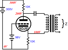
Is there a name for this circuit and can anyone provide an example of it in a piece of gear? I’m not saying it’s novel but I did just come up with it unprompted. The unity gain push-pull output is its greatest asset - great back end for a mic pre of course. Good input headroom, output headroom only limited by B+, but assuming 200V it could probably do 30dBu at the trafo primary. Is its drive capability limited to its quiescent current, or does it behave like an SRPP or WCF to some degree?

IMG_7570.jpeg

EDIT: I may have screwed up the percentages of B+…might need to be 33%/33%/33% and 270V, which puts the upper follower and its resistors into 90V proper, with the lower cathode at 90 and the lower anode at 180. 200V would be a squeeze. Either way the upper and lower resistor values won’t be matching, so they shoulda gotten labeled RkA1/2 and RkB1/2. And thus it can not exceed its quiescent current at the output. But hey, still unity!

EDIT 2: From post #3, rule of thumb for starters is:

LOWER Vk .375 * B+
LOWER Va .625 * B+
UPPER Vk .750 * B+
UPPER Va 1.00 * B+

…and pick your Vgk (Rgk) first, as it will always be the same.
 
Last edited:
Here’s a better example. You have to squeeze down the lower valve’s Ri to make room for the upper. I guess this puts out 7.4mA, so that would be about 17Vpk into a 2:1 trafo driving 600R, i.e. 12Vrms / 23.8dBu at the primary and 6Vrms / 17.8dBu at the secondary.

IMG_7571.jpeg
 
Okay! It all makes sense. You get twice the level for no additional current and no real noise gain into light loads (duh, differential). No benefit into heavy loads AFAICT. It’s nice to find something for output that helps keep internal levels low and headroom high, without adding gain at the end.

Really flirting with grid current here into the top triode, just wanted to see if this was doable on a 200V supply. Looks like it is, barely.

IMG_7572.jpeg
Way higher Zout on the bottom than on the top, but I assume the trafo takes care of the imbalance. 150 ohm output here, perfect. About the same as a bypassed SRPP with plenty of feedback and the same trafo, I think.
 
Last edited:
I think you can dispense with one of the 47uF outou caps and both 100k bleed resistors.

Interesting circuit. Not seen that before.

Cheers

Ian
 
y post your application! i amended the first post with the correct B+ ratios at each node.
Maybe as an output stage for my small console (you may have seen the thread) if I'll need more power (I don't have too much to spare).
Or maybe I'll consider 2 PL95 or PL84's (per channel) in SRPP (like the Philips 800 ohms OTL system, so I won't need a transformer, and they almost throw those TV tubes at your head!).
I'll look for the most cost-effective option; my goal is to make a small valve mixer for as dirt cheap as possible without being all too crappy.
 
Maybe as an output stage for my small console (you may have seen the thread) if I'll need more power (I don't have too much to spare).
Righteous. This circuit’s achilles heel is B+. I think that a regulated 240V is the way to go, which conveniently divides into eight. Lets the negative CF have more swing, allows for a Vgk closer to the 2V operating curve. Heater at 1/2 HT, I’d say.

You could also set up a bypassed SRPP for a gain of nearly mu, but operate it at 50% feedback as an anode follower, into the same 2:1 trafo, which would net the same unity output. In other words, 10K grid resistor, 20K from the SRPP out into the grid. 5x those values if you’re driving it with a plate.

Edcor 2:1 o/p is cheeeeeep.

“Strauss Follower” unless one of the ancients stole my idea.
 
Last edited:
You could also set up a bypassed SRPP for a gain of nearly mu, but operate it at 50% feedback as an anode follower, into the same 2:1 trafo, which would net the same unity output. In other words, 10K grid resistor, 20K from the SRPP out into the grid. 5x those values if you’re driving it with a plate.

“Strauss Follower” unless one of the ancients stole my idea.
I'm afraid I don't really understand that... Could you draw it please?
And how is it done the simplest way, to get the heater at that level?
 
I'm afraid I don't really understand that... Could you draw it please?
And how is it done the simplest way, to get the heater at that level?

https://groupdiy.com/threads/anode-follower-as-trim-stage.86427/

a voltage divider from B+ to ground with a capacitor from the center node to ground and the center node tied to the center tap of your heater supply. don’t power a common cathode stage heater like that though, use regular 1/4 HT elevation if all tubes share a heater supply.
 
Also, you can save half a triode and let the upper element be a depletion mode mosfet, because it just doesn’t matter in this application. No need for heater elevation. If you put the differential follower after an inverting stage, the upper element — with its lower output impedance — gets to drive the positive side. Pardon the crappy scan.

IMG_7576.jpeg
^ that grid current note is optimistic, there will be distortion as you approach and exceed 24dBu each side.

This output stage makes the difference between 66dB and 72dB maximum gain in the preamp i’m working on. With no noise penalty. And it allows me to run the preceding stages 6dB lower, which is great for current draw and internal headroom. 💯
 
Last edited:
Grid current is always a potential problem with low gain stages simply because they need quite a high drive voltage. I prefer running a 6922 as an SRPP. Well over 20dB gain, true push pull output and no grid current issues. The penalty is of course higher distortion.

Cheers

Ian
 
Any intelligent fool can make things bigger, more complex...
split-load%20phase%20splitter%20with%20transformer.png
 
11.5mA (sure), 2500 ohm output (meh). Could buffer the plate with a CF that utilizes the full height of B+ and run both stages at 6mA for 150 ohms, that would avoid the headroom limitation of my circuit on 200V. 34dBu primary, 28dBu secondary, into a 600 ohm load.

Alternately, a lower draw cathodyne splitter (3mA), into a CF stack (7.5mA). 30dBu primary, 24dBu secondary, into 600 ohm.
 
Last edited:
11.5mA (sure), 2500 ohm output (meh).
Not sure where you get that figure. Drive impedance to the transformer is roughly 2/gm, not 2500 ohms (considerably lower than your circuit).
Could buffer the plate with a CF that utilizes the full height of B+ and run both stages at 6mA for 150 ohms,
Or just put the two triodes in parallel. The point is, more headroom, lower output impedance, fewer parts than a totem pole.

It's not entirely clear what the push-pull drive actually buys you, when any ordinary unity gain driver is gonna have very low distortion anyway🤷‍♂️
 
Last edited:
Not sure where you get that figure. Drive impedance to the transformer is roughly 2/gm, not 2500 ohms (considerably lower than your circuit).

I hadn’t read this bit, and 10K / 4 = 2500.

IMG_7577.jpeg
It's not entirely clear what the push-pull drive actually buys you, when any ordinary unity gain driver is gonna have very low distortion anyway🤷‍♂️
It buys a unity gain output instead of the 6dB loss through a 2:1 trafo that a WCF or fully fed back SRPP would net.

Aw man, i forgot about needing to add a large grid block with the cathodyne. Kind of a lot of johnson noise in a mic pre, even unamplified.
 
Last edited:
It buys a unity gain output instead of the 6dB loss through a 2:1 trafo that a WCF or fully fed back SRPP would net.
Good point. Is 2:1 a standard for 600 ohm transformers? I don't know what's available.
Aw man, i forgot about needing to add a large grid block with the cathodyne. Kind of a lot of johnson noise in a mic pre, even unamplified.
I don't think you need a particularly large grid stopper?
 

Latest posts

Back
Top