Check this mic pre

GroupDIY Audio Forum

Help Support GroupDIY Audio Forum:

This site may earn a commission from merchant affiliate links, including eBay, Amazon, and others.

audio2

Active member
Joined
Jun 22, 2007
Messages
35
Location
Hollywood
Hey ya'll. I need some of the pro's to check this mic preamp design layout before i make some boards. its nothing special at all just out of the INA217 data sheet.
Anyways it will consist of 48v on off switch, phase reverse, -20dB pad. Balanced output and a send output which will eventually go to a compressor i design. The compressed signal will then go back to the line driver for balanced output or with a jumper can be used to send two signals, one compressed, one not.
The board 3.5in X 3.5in. Hopefully will be something ideal for putting together a 3ru, 8 ch pre , or a 4ch pre. So input would be great.

thanks
a2-1.jpg
[/img]
it 2 sided. I ran most of the signal on the top layer in red. all film caps are 100nf at opamp supply pins. Con3 will go to a grayhill selector for mic pre gain.
 
The layout looks good but the ground plane should be on top
and the signal traces on bottom. Just an idea to consider.


RonL
 
[quote author="audio2"]Hey ya'll. I need some of the pro's to check this mic preamp design layout before i make some boards. its nothing special at all just out of the INA217 data sheet.
Anyways it will consist of 48v on off switch, phase reverse, -20dB pad.[/quote]
Not a pro but let me still suggest to change 'phase' into 'polarity'.
 
[quote author="rlaury"]The layout looks good but the ground plane should be on top
and the signal traces on bottom. Just an idea to consider.


RonL[/quote]
ok, i wasn't sure how they normally go about that. i'll fix that. thnks, but whats the reason for that?

well phase and polarity go hand in hand dont they? i mean if you reverse or flip the polarity in a sense you flipped the phase no? (or i guess its phase when comparing two channels with respect to each other? then your dealing with phase right?) Otherwise yes, i guess it would just be polarity, if it was just 1 channel. i dont know you got me confused now.
Pro or not, learn me why it should be changed. thnks
 
[quote author="audio2"]well phase and polarity go hand in hand dont they? i mean if you reverse or flip the polarity in a sense you flipped the phase no? (or i guess its phase when comparing two channels with respect to each other? then your dealing with phase right?) Otherwise yes, i guess it would just be polarity, if it was just 1 channel. i dont know you got me confused now.
Pro or not, learn me why it should be changed. thnks[/quote]

Rane's Pro Audio Reference says it like I couldn't myself:
polarity
A signal's electromechanical potential with respect to a reference potential. For example, if a loudspeaker cone moves forward when a positive voltage is applied between its red and black terminals, then it is said to have a positive polarity. A microphone has positive polarity if a positive pressure on its diaphragm results in a positive output voltage.
[Usage Note: polarity vs. phase shift: polarity refers to a signal's reference NOT to its phase shift. Being 180° out-of-phase and having inverse polarity are DIFFERENT things. We wrongly say something is out-of-phase when we mean it is inverted. One takes time; the other does not.]
Or as said in the Sweetwater tech-info (just quoting a part of the page):
Phase as it applies to microphone preamps!
...
There are a couple of issues to address here. First we should make the distinction between phase and polarity. The switch that you are referring to should be called a polarity switch. Though it is commonly called a phase switch (this is an industry wide problem, not something you got wrong), really all it does is reverse the polarity of the signal.
...

Some more:
http://www.sweetwater.com/insync/word.php?find=polarity

...but skip this one, imho it's not ph(r)ased fully correctly there :oops:
http://www.sweetwater.com/insync/word.php?find=phase


Regards,

Peter
 
Peter you are correct, i changed it. Though i agree it is misleading, but by flipping the polarity (which yes has nothing to do with time) it will effect the phase. Actually now that i think about it a polarity switch is really just a "lets hope its a 180 degrees off" switch. right? i mean if it aint exactly 180 degrees off your still gonna have some phasing. and then on top of that if it was 180 off you'd notice almost immediately cause there would be phase canceling. So now i have to ask really what good is this switch for? Should i just take it out of the layout?

anyways heres the board again with the fixes
audio2pre.jpg
 
The ground plane should be on top and the signal traces on bottom.
I'm not sure if the order of the layers matters much (I think having the ground plane between parts and traces directs stray capacity between them to ground, that's why the ground plane is usually on top) but indeed having all traces on one layer and ground on the other would be the optimum solutions with respect to ground plane efficiency. Personally I've found that for most (not super-simple) circuits the restriction of having to fit all traces into one layer just leads to needless routing complexity and longer traces which might hurt more for audio than a somewhat splitted ground plane (we're not dealing with 10 MHz signals and 100 MHz amplifiers where life might look different). Usually I try to about partition the number of traces between top and bottom layer (with one layer--usually the top--having more power traces and the other more signal) and then fill both layers with a ground plane. Seems to work very well.

Four or even six layer boards would be cool but oh the $$$s...

Can't read the schematic, sorry. Post a link to a larger (not downsampled) image.
Although the author of this thread seems not to be too cooperative with this respect I can't resist to note a few things on the schematic:
* There should be a small resistor in series (between power supply and C5) with the 48 V line. Otherwise C5 won't have much effect and the phantom power might be noisy. About 200 ohm is fine.
* I'd make R3/R4 much larger, probably 100 kohm. This will greatly enhance low-frequency CMRR as the mismatch of the input AC coupling capacitors will matter much less. If you want lower input impedance, put a resistor across the lines (and not to ground) and befor the coupling capacitors.
* The protection diodes should be of a robust type (not sure what you intended to use), e.g. 1N4007GP--small-signal parts might not survive a dead short with phantom power on (if this ever happens is another question). In addition to this, a pair of small current limiting resistors (4.7 ohm) might prove helpful.
* Where is your RFI protection at the input? At least a pair of 470 pF to chassis ground is a must.
* Do you really want to use INA217? I think there are much more capable (with respect to distortion and noise) chips out there.

Samuel
 
[quote author="audio2"]So now i have to ask really what good is this switch for? Should i just take it out of the layout?[/quote]

Hi,

Polarity-switches are indeed no guarantee at all for fixing phase-problems. There'll be many people who live in this assumption, but there's no free lunch. Re-positioning a mic is not too big of a task though and fixes phasing problems where they originate.
A polarity-switch can and will function as a 'let's see if by chance it's less worse if we flip the polarity', but that's it.

It's 'fully' of use though if you have for instance parallel paths going on in which one of the two paths happens to swap polarity - so then you can correct it in your mic-pre.
An example of this might be a snare-bottom-mic, you'll usually want to swap the polarity on that, but note that there still may be a 'phase-residue' left.

Regards,

Peter
 
I'd increase the actual value of the pad's resistors some to reduce the tonal effect of the low-Z pad when actuated, and I'd put the phantom power resistors out at the XLR, rather than after the pad and polarity.
 
[quote author="Dan Kennedy"]I'd increase the actual value of the pad's resistors some to reduce the tonal effect of the low-Z pad when actuated, and I'd put the phantom power resistors out at the XLR, rather than after the pad and polarity.[/quote]

what values would you suggest for the pads?
the 48v resistors are before the pad and polarity. unless im misunderstanding you.?
 
Peter - thanks for the reply. Good point on the bottom snare mic.

Samuel - thanks also for your reply and input.
I was gonna use 1n4148 diodes for protection. I have used them before with no problems. Good looking on the resistor before the cap on the 48v line. Totally missed that. As for R3 and R4 are you talking about the resistors for the input bias? Sorry i just got sloppy and labeled them different on my board. :? 100k? TI data sheet suggest 2.2k. I ask only cause im not a vet when it comes to electronics.
I'll add the RFI protection. Thanks
As far as INA217 goes, it doesn't have to be "the" chip for this board. The THAT1512 or SSM2019 should work as well with little or no mods.
 
[quote author="Dan Kennedy"]I'd double the resistor values in the pad.[/quote]

This is an interesting deviation I see between designers. For example, JLM uses 470ohm series resistors. NewYorkDave uses 1k ohm series resistors.

The latter presents a load of 2K to the microphone, which should keep some transformer-balanced mic circuits happier. I would venture to say that any well-designed electronically balanced output should drive 940ohms with ease.

On the other hand, the SM57, which specs a 250ohm output impedance has been reported to sound better loaded with 600ohms.

If only I had all day to do listening tests of all these possible combinations.
 
Dan take a look at where BP1 & BP2 are, down towards the bottom left on the board. The phantom resistors are just before the caps. I think i understand what your saying but im not sure really. 2- 6.8k resistors are just after the xlr inputs. i'll get a close up shot and post, sorry i know this ish is hard to read.


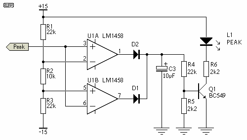
I was thinking of putting a peak indicator on the board. I used the schema from ESP. can someone double check my layout please. i kinda stuffed it in there.
p30a_f8.gif

a2prerev4peak-1.jpg
 
thinking about it now, i would want the peak indicator before the INA217 right? or do i want to sense the output of it? dang sorry for the newb questions guys.
 
ya my bad, like i said i got lazy. :roll:
sometimes i work ass backwards and start on the layout. I dont know why but it seems easier for me, probably its more a visual thing, i have no idea. Good lookin out though Dan.

Dan i was wondering would 47k resistors do the job for Line to mic padding?
 
Sure they would, but the bigger question is why?

There are artist and sonic benefits from running a line signal back thru a transformer coupled device, or tubed or both, but this amp isn't going to impart anything sweet.

Not to cut it, but the only artifacts you'll get out will be the tiny nasties that are left in the IC's.

I'd just route the line signal to the output jack directly, or if what you're really after is a balanced to single-ended conversion, I'd do it with a part optimized for that function, like the THAT In-Genius, or one of the other line level receivers available.

Back in the '80's & '90's, one of the mods I did to lower cost boards was to add a small circuit board to the front end with a line receiver circuit and switching that disabled the padded line to mic-pre issue. All of my clients preferred it.
 

Latest posts

Back
Top