Collins 26C Analysis

GroupDIY Audio Forum

Help Support GroupDIY Audio Forum:

This site may earn a commission from merchant affiliate links, including eBay, Amazon, and others.

DaveP

Well-known member
Joined
Nov 8, 2005
Messages
3,175
Location
France
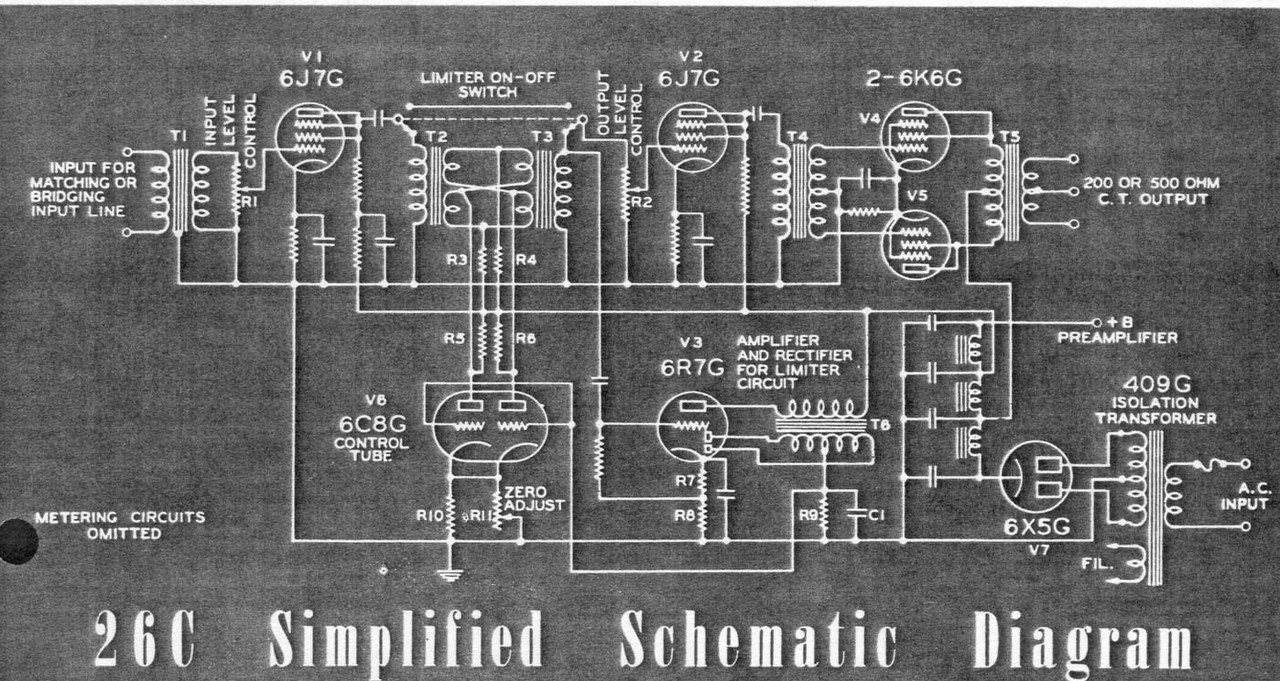
Many years back, we made a Groupdiy 26C as a fundraiser and I have always been fascinated by its unique design. I will attempt to find out its secrets and explore the possibility of improvements to this unique pre-war design. This is the schematic:-
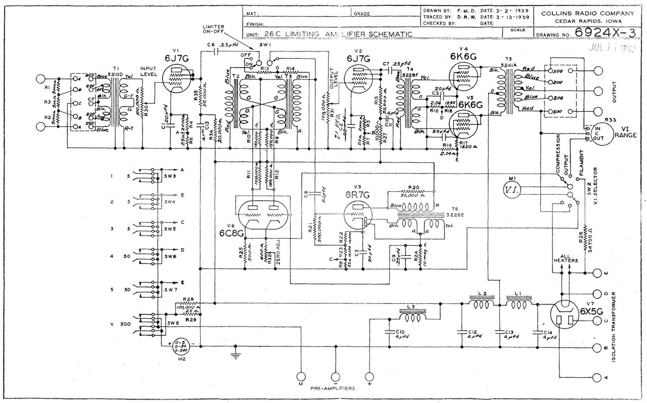
We also have the manual for info, attached. It cost $10 when the average wage was only $23/week !
I have also attached the sales literature which gives a fuller explanation of how it works.
best
DaveP
 

Attachments

  • 26C-Manual.pdf
    2.7 MB
  • 26C Sales Lit.pdf
    4.2 MB
Thanks for sharing Dave ! Is there a typo regarding the price ?
No typo, its letters not numbers.
Can you expand on the 26C fundraiser unit ? How was it organised ?
https://groupdiy.com/threads/groupdiy-bridge-compressor.47703/
This is the link to the start of the thread back in 2012.
I made it with suggestions and advice from other members then shipped it to Doug Williams in the US for testing. He corrected some problems and sold it 6 years later, after expenses it made $400 for the forum.
best
DaveP
 
I still have an original 26C mkII. The post-war 26W is an update of the same compression concept, behaves similarly, with greater range. Some of that range in the original 26C is set by the relationship with the overload point of the input tube, 13dB max. (see manual page 12).

Sample of 26W:

 
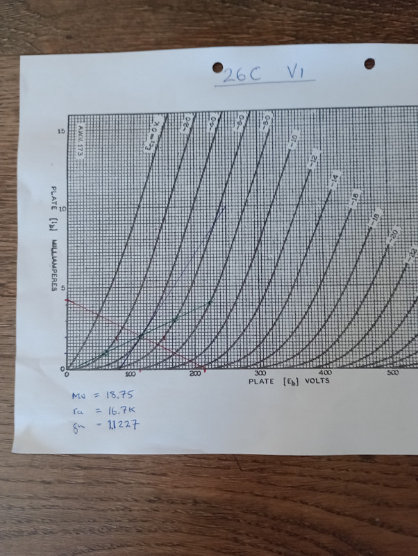
Page 16/32 of the manual gives the HT/B+ as 255V and the current for V1 as 2mA. There is a 20k decoupling resistor R34 which brings the voltage down to 215. I have charted the working point below:-

From this it's possible to see that the figures check out OK, the 2k cathode resistor R4 neatly crosses the line -4V and 2mA.
From the chart, the tube parameters can be calculated as mu 18.75, ra 16.7k. These figures are important to calculate the gain and the source resistance for the transformer load, more on that later.......

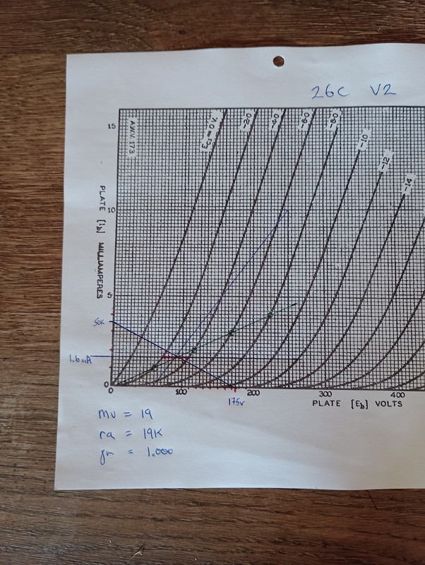
Trying to do the same for V2 encounters an error! The problem is that the decoupling resistor R27 (10k) is not listed in the parts list page 22/32, it is marked as a Volume Indicator resistor of only 3419 ohms. In order to achieve the 1.6mA stated in the manual, R27 would need to be 50k and the decoupled voltage 175V, this gives a cathode voltage of 2k x 1.6mA = 3.2V.

best
DaveP
 
Last edited:
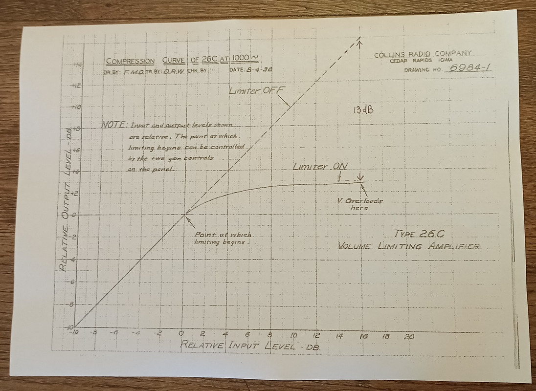
As Doug mentioned in his post, the overload point of V1 determines the maximum compression, I have marked it on the Compression chart:-

You can see that this point comes 16dB after the verge of compression.
The cathode voltage of V1 is 4V, so the maximum swing is 8Vp-p. This corresponds to an input voltage of 8/2.828 = 2.828Vrms.
16dB is a factor of 6.311, so V1 at the verge of compression needs 2.828/6.311 = 0.448V

The quoted spec on page 8/32 is that the minimum input level to arrive at the verge of limiting is -35dB. Remembering that these figures are based on the old 500 ohm 6mW system and that -35dB is a factor of 56.3, so 1.732V/56.3 = 30.8mV minimum input level.

The input transformer is wound for 500/200 ohms so the 200 ohm ratio will be the one referred to for the -35dB minimum input because the gain will be greater than for the 500 ohm winding. So we can calculate the gain of the 200 ohm input as 0.448/0.0308 = 14.56 :1
The ratio between the 500 and 200 ohm primary is SQRT 500/200 = 1.581, therefore the ratio of the 500 primary is 9.2 :1 The secondary is therefore 42.4K.
best
DaveP
 
Last edited:
There is more info to be found from V1, but first we must make assumptions about the pair of bridge transformers used for T2 & T3. The sales literature from 1938 says that they are standard production models, but this could mean 600:15k or 15k:15k or other ratios, one thing is certain, the overall gain is unity whichever transformers are used (less normal transformer losses say 4%) because they are reverse connected.

The four 150k resistors in the bridge are in parallel so they represent a load of 37.5k reflected back to V1 if the ratio is say 15k:15k, if the transformers are 600:15k then the load reflected back will be 37.5/(15000/600) = 1500 ohms, but V1 would not be able to drive such a low load in this case. So I will assume that the transformers are 1: 1 matching types regardless of the actual impedance.

We can now use the normal gain equation for V1. mu x RL/ RL + rp. 18.75 x 37.5/37.5 + 16.7 = 12.97

f = Z/(2*Pi*L)
enables us to calculate the Inductance required in the primary. The source resistance is rp//37.5k (the reflected impedance), which gives 11.55k. The sales lit. says the frequency response is within 2dB from 30 - 10kHz, so lets say for example that it is -3dB at 20Hz.

Therefore L = 11550/20 x 6.283 = 91.9 Henries, this seems like a reasonable figure for a pre-war high quality transformer, but if the limit was 30Hz then the primary inductance would be 61 Henries.
best
DaveP
 
I've been watching this thread (and the original about the 26c) with great interest! As someone who has spent the past 50+ years as a broadcast engineer, audio processing has always been a specialty of mine. I have quite a collection of restored processors, mostly in stereo pairs. These include a pair of RCA BA-6a Limiters, a pair of Gates SA-39 limiters, a pair of Gates Sta-Level AGCs, and a pair of Collins 26U limiters. (also a good deal of later solid-state stuff mixed in)

The Collins 26U is a favorite of mine. It's fascinating to me how different it is from the 26C! Of course, the 26U is vari-mu based, as the 6386 tube was all the rage during those days. The 26U is really nearly the same as a Gates Sta-Level in most ways, with steeper slopes, and faster attack and recovery times (stock from the factories). It's not difficult to make one sound nearly the same as the other.

Until seeing this (and the previous thread about the 26C) I had never seen a bridge-transformer configuration used as a gain control element. I'd like to thank DaveP. and Doug W. in particular for educating me on this unusual (to me) method of limiting!

I'm wondering if this gain control scheme was used in any other limiters? Perhaps later Collins units, up to the 26U? I do so love the history of audio processing!

Thanks again,
Dave O.
 
Now we have the gain of V1 at 12.97, we can calculate the voltage appearing at V2 and V3 at the verge of limiting.
Input voltage at verge = 0.448Vrms so output into T2/3 is 0.448 x 12.97 = 5.81Vrms. If we assume that each transformer loses say 4% it will give an output from T2/3 of 5.81 x 0.96 x 0.96 = 5.35Vrms, we will come back to this later regarding V3, but for the moment we will look at the output stage.

Each 6K6 cathode is at 22.5V so the maximum input swing is 45Vp-p or 45/2.828 = 15.91Vrms. There are two secondaries to the T4 phase splitter transformer so the total secondary voltage for maximum output at clipping onset is 31.8Vrms. As V2 has 5.35V available, it has plenty of reserve gain on the output level control, so further amplification by T4 would not be necessary, so I will assume it is something like 15k:15k ct.

The maximum output level is given as +20 dB, which for a 500 ohm load is 10 x 1.732Vrms or 17.32Vrms. The recommended load for the triode wired 6K6 is 7.5~8k, but it could be 10k or more. If it is 8k:500, then the ratio would be 4:1 making the primary voltage 17.32 x 4 = 69.28Vrms so the gain of the 6K6's would then be 69.28/31.8 = 2.17

If the OPT is 10k:500 then the ratio is 4.472 and the primary volts would be 77.45rms making the gain 2.43. The quoted gain of the triode wired 6K6 is only 6.8 at a higher current, so these figures are probably fairly close to the actual figures. The effect of the various load lines under class A B conditions will have to be looked at graphically later.
best
DaveP
 
The earliest schematic from the sales lit. dated 1938, shows a combined cathode resistor/cap for the output 6K6's. It also shows that the V2 plate resistor was not decoupled and was connected straight to the B+, this might explain the V2 plate resistor anomaly mentioned in post #6:-

The schematic at the start of this thread is dated 1947 (could be 42?). It's also worth mentioning the by-pass cap on V2. The parts list value is 30nF, but the schematic shows 20nF, this would have given a treble boost from 2~4kHz, presumably to correct transformer losses?
best
DaveP
 
I see that date as 1942, and the one from the sales sheet as simplified. The first schematic I drew up around that simplified version, and there were many additional complexities. 26C-1 and 26C-2 have a number of differences as well. The bridge resistors on the 26C-1 I drew out were 47K and looked original, and the ratio on T2/3 was greater.

26C-2 used the same transformer for T2/3/6, described as 20K:80K, pri 490H, sec #'s 1/2 each 620H.

output is indeed 10k:500.

The individual transformer specs are all 30-10K.
 
Back
Top