Comments on EQ schematic

GroupDIY Audio Forum

Help Support GroupDIY Audio Forum:

This site may earn a commission from merchant affiliate links, including eBay, Amazon, and others.

dspruill

Well-known member
Joined
Oct 11, 2006
Messages
161
Location
Jacksonville, Florida U.S.A
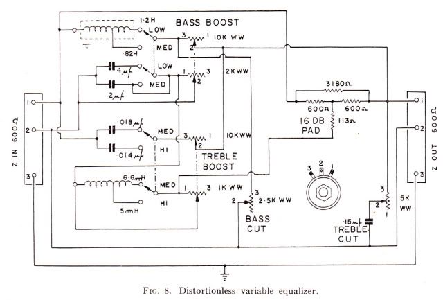
Hi everyone, I came upon this schematic and thought it might be fun to put together. Can anyone give me some general feedback about how effective this circuit might be as in "is it worth building?"
Please forgive my noobness, but I was intrigued because I saw this circuit used inductors, so I was curious.

Thanks
David

Carlos_Moura_Distortionless_EQ-1.jpg
 
Very old school 600 ohm in, 600 ohm out, passive EQ. 

Perhaps of historic interest. It probably won't be easy to source those parts. I can't recall the last time I saw/used a wire wound rheostat. You may be able to use two inductors in series to replace the tapped inductor, unless they need to be on a common core to work the same in that circuit.

I love that they call it "distortionless". I guess that is all relative, blame the distortion on the make up gain stage. 

JR

 
The fact that there are two dual pots with different resistance values for each section (10K/2K & 10K/1K) might be an issue unless you used discrete resistors on a switch.  I don't see why you would need to use wire wound pots though, we have decent carbon and plastic pots these days.

It's probably OK as a simple tone control circuit, it's similar in response to a lot of "Top" and "Bottom" controls on early mixers - Decca, BBC, EMI  etc.  although it's not something you couldn't get with using one of Ian's Poors Man's Pultec circuits IMHO.
Interesting to see it though, thanks  :)


And Ian's right, it took me a few minutes to figure out what was going on, it's drawn so strangely  :eek:

 
mulletchuck said:
Why is this circuit considered "oddly drawn"?  What what it look like if it were drawn better?

I think I would draw it myself with the reactive elements placed appropriately around the 16dB insertion loss pad. 
For instance, the upper pot sections and reactive elements of the Bass and Treble boosts are just in parallel with the 3180R bridging resistor of the pad but I was following traces around for a minute before I realised this.  The eq became easy to understand once the penny dropped.

Maybe it's just me? 


Edit: By the way, one thing that is a bit ahead of other earlier constant impedance (600 ohm or otherwise) EQ's with this one is the fact that there isn't double the insertion loss for Bass and Treble.  Early constant Z eq's had cascaded sections for treble and bass whereby the pad losses (and therefore the amount of maximum boost) were added together.  So, a +10dB Treble and +10dB Bass resulted in a 20dB total loss.

Here, the two bands are stacked so the insertion loss is less.  It states it's 16dB but a rough thumb calculation looks like maximum boost is closer to 10dB.  **


My REDD17 had a similar topology although it was centred around 200 ohms rather than 600 and the eq was stepped in increments on a switch with boost and cut on the same switch rather than separate pots. 
My desk was made in 1957 or 1958 but I've seen similar eq's from just a few years earlier where the insertion loss was indeed twice. 

**  Edit:  My quick thumb calc. forgot to terminate the network.  See later posts.
 
mulletchuck said:
Why is this circuit considered "oddly drawn"?  What what it look like if it were drawn better?


All passive attenuators are basically variations on a pot divider:

Code:
IN-------/\/\/\/\-------------OUT
            R1       |
                     >
                    <  R2
                     >
                     |
                     |
                    GND

The nominal loss in this pot divider is usually between 15 and 20dB (R2/R2+R1). To get boost you either place a frequency dependent impedance in parallel with R1 or in series with R2, both of which will reduce the attenuation. To get cut you place a frequency dependent impedance in series with R1 or in parallel with R2, both of which will increase attenuation. The frequency dependent impedances can be simple inductors, capacitors, RC or LC networks depending on the shape of the boost or cut you want. Even with no frequency dependent components in cirucit you still have the nominal attenuation of the pot divider so you need to follower the EQ with a gain make up amplifier to restore the overall gain to unity.

So, in my view, the proper way to draw these circuits is so you can easily see the pot divider and the connections to it of the various frequency dependent impedances.

Cheers

Ian

P.S. Pls excuse very poor ASCII art.
 
ruffrecords said:
Have I missed something or is it possible with the bass cut and boost pots both set to 3 that the output is shorted?

My eyes hurt from staring at it sideways but I think so!

Since we've already shelled out and had 200 of 'em built, let's call it a feature!  It'll disscourage the users from trying something as silly as boosting and cutting at the same time.


What's that you say?  The Pultec lets you boost and cut at the same time?

Merd!


dspruill said:
What would be the result is I used four separate pots instead of the 2 dual pots?

David

David,
there are already 4 pots, 2 for each frequency - boost & cut.
The issue is with the boost pots which are duals of differing values per each pot section.  They control two sets of reactance components simultaneously (series and shunt) because the boost is of the peaking type response.  The cut pots are single deck types because cut is just a shelving response.

Cheers.

 
Thanks Jean,  its the boost pots I meant. I was wondering what would happen If I replaced the two dual pots with four individuals. 2 10ks a 2k and a 1k. They wouldn't track together as shown, but would it work somewhat, or not at all?

Thanks,
David
 
And here's a sim. showing the difference between having the 1K/2K halves and not.  Blue lines are without.
To make it easier to read, only the lowest and highest frequencies are shown.

Since the 10K pot halves do the bulk of the work, if you made this with separate pots, you could label the 10K's as "Boost" and the 1K/2K pots as...  "Steepness" or "Curve Bending" or whatever sounds cool to you  ;)
 

Attachments

  • BoostDifference.jpg
    BoostDifference.jpg
    138.6 KB
Incidentally, if the source generator impedance is set for 600 ohms, there's no difference in eq response from when having a source impedance of zero in that maximum boost stays at 10dB although insertion loss goes up from 10dB to 16dB.
If you terminate the network with 600 ohms, the maximum amount of boost then goes up to almost 16dB and the insertion loss is also 16dB.

Also, when at 16dB boost, the frequencies move outwards as you'd expect.  But if you turn down the pots and compare the curves at 10dB (apples to apples IOW), the curves are the same as without the 600R termination.  Hope this makes sense?  :eek:

So, if 10dB boost is enough for you, or you want to keep the insertion loss down, then use a make-up amplifier with a bridging input impedance (10K or so) and keep your driving impedance down below 100 ohms. 

The real DCR of the inductors will slightly change the curves too but I modeled them as ideal chokes for this sim.

I'll leave the rest as an exercise for you or others  ;)
 

Latest posts

Back
Top