D-AOC PCBs - the building and help Thread

GroupDIY Audio Forum

Help Support GroupDIY Audio Forum:

This site may earn a commission from merchant affiliate links, including eBay, Amazon, and others.
[silent:arts] said:
What are you using for the transformer links?
They shouldn't short anything out (use insulated wire).

To be honest I would completely redo the wiring.
For testing purposes I used  thin paint isolated wire from a prototype wire pen. It’s too thin to spot in the picture. I made sure they wouldn’t short actually..

I will rewire it once again out of the chassis with bigger cables if that’s what it needs
 
[silent:arts] said:
To be honest I would completely redo the wiring.

Hey volker,

i rewired the transformers with proper insulated wire, same result, absolutely no sound. But now i know the problem. It is definitely the wiring of the lundahls!

I took a wire of the input transformer (pin 1) and tried to get some sound of the unit by connecting it differently, and i got sound !
Although it was really dull sounding (like a high pass filter), the unit was compressing as expected. Now i should check this schematic again ???

Is it possible that the input wiring needs to be done differently?
Should i try the one mentioned on the website of lundahl?
I am sorry but i got very little experience with transformers, i hope to solve this issue soon !

thank you again! :)
 
i replaced the transformers and relay assembly from the non-working unit and now i get no compression anymore. only sound is passing. it may be related to my bypass wiring, which also toggles LED's. I checked the relays and they click when toggling the switch. What would be the reason that my meters show compression but the bypassed sound is getting routed to the output xlr's?

i am really desperate right now. now i'm stuck with two non working compressors  :-[ :-[ :-[
 
weiss said:
i replaced the transformers and relay assembly from the non-working unit and now i get no compression anymore. only sound is passing. it may be related to my bypass wiring, which also toggles LED's. I checked the relays and they click when toggling the switch. What would be the reason that my meters show compression but the bypassed sound is getting routed to the output xlr's?

i am really desperate right now. now i'm stuck with two non working compressors  :-[ :-[ :-[

Do a continuity test with the relay boards. Bypass should give you contact between Pin 2, 3 on the input and respective pins on the output XLR and engaged should not, as you know. Verify that then maybe the next step is to bypass the transformers and go straight in and out of the PCB. Also verify that signal is present at the input header of the main board. Also you could wire an XLR straight to the board with no relays. You may have already done all of this but it seems that this is one of those cases where you get to start over and stare at the board until you see the problem. I've been where you are in the troubleshooting process and it sucks.

Thanks!

Paul
 
Potato Cakes said:
Do a continuity test with the relay boards. Bypass should give you contact between Pin 2, 3 on the input and respective pins on the output XLR and engaged should not, as you know. Verify that then maybe the next step is to bypass the transformers and go straight in and out of the PCB. Also verify that signal is present at the input header of the main board. Also you could wire an XLR straight to the board with no relays. You may have already done all of this but it seems that this is one of those cases where you get to start over and stare at the board until you see the problem. I've been where you are in the troubleshooting process and it sucks.

Thanks!

Paul

thanks for your help and ideas, paul!
pin 2 on the inputs give me continuity to the output even in bypass mode, there must be a connection somewhere  ???
 
i bypassed the transformers, one channel is compressing a bit, but not really much - one channel completely bypasses sound and controls aren't responding. Next, i'm gonna bypass all the relays and see what happens. I don't get why one relay won't switch off...
 
Yes Ansgar, bypass the iron and the relay board and do some basic tests with your main PCB first. If everything is okay, bring back the rest, step by step and see where your problems starts again. Stay strong, good luck  8)
 
rock soderstrom said:
Yes Ansgar, bypass the iron and the relay board and do some basic tests with your main PCB first. If everything is okay, bring back the rest, step by step and see where your problems starts again. Stay strong, good luck  8)

Thanks for helping me out. These little things really drive you crazy.  :eek:
 
Everybody knows that feeling, it sucks... :mad: 
If you still have problems with weak compression, then cancel the slope board and just use a blue LED antiparallel to the vactrol. Keep it simple, try to get one channel 100% working.
 
thank you guys,

i completely removed the relay section and bypassed the iron, everything worked like expected (i only found out that one of the 24 step ebay switches has one wrong resistor value soldered on)
i inserted the iron back in the circuit and still everything working fine.

Any ideas what i could check on the relay boards?
 
I also gave the ludahls another try. Still not working. The edcors work fine so the wiring must be faulty.

Can anyone  help?
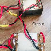
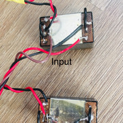
My current wiring:


Thank you
 
I checked only your input transformer wiring yet, but I think there is a mistake!? I am not sure but I would do it like this for a 1:1 setup.
 

Attachments

  • IMG_2097.JPG
    IMG_2097.JPG
    1.9 MB
This is my sniffer, a handy tool to trace signals in circuits. Basicly a battery powered headphone amp with a probe. Easy to build and a real weapon for finding bugs in your signal flow. Just plug in some music and follow it with the sniffer. Very effective  8)
 

Attachments

  • image.jpeg
    image.jpeg
    1.2 MB
Hi Weiss,

Keep your build tidy with this PCB: https://www.ebay.de/itm/Universal-LUNDAHL-dual-signal-transformer-board/273807500299?hash=item3fc032e40b:g:uA0AAOSwEqVcO3DM
It works just with input lundahl trafos, but it can be useful to connect them in the right way with a few euro.
 
I checked for continuity on the relay boards but i can't make out any obvious mistakes.
Handy thing, your sniffer!  :D

Unit-8 said:
Hi Weiss,

Keep your build tidy with this PCB: https://www.ebay.de/itm/Universal-LUNDAHL-dual-signal-transformer-board/273807500299?hash=item3fc032e40b:g:uA0AAOSwEqVcO3DM
It works just with input lundahl trafos, but it can be useful to connect them in the right way with a few euro.
Nice find, gotta try this next time  :)
 
So i found out one of my Omrom relais was defective. No idea how that could have happened. Are they that sensitive to heat?  ???
Seems i'm one step further trying to get everything working again.

- I really love what it does to the lower frequencies. It really puts it right where it needs to be. But i get the feeling the high frequencies get attenuated a lot. I am using the Edcor transformers at the moment. Will compare it to the lundahls soon.

- The overall level is much lower compared to the bypassed signal. I really have to turn the switches all the way to make up the loudness, even with no compression going on. Is that normal?

- I'm not able to send a mono signal through the compressor and receive it back how it was. It doesn't stay mono somehow, but i guess i still need to do the calibration before i can actually call this a problem..

- The wiring of my lundahl output transformers was always working! Only the input isn't correct yet. I already tried several options, amongst others the official scheme from lundahl (https://www.lundahltransformers.com/wp-content/uploads/datasheets/1540.pdf). Does anyone have some other ideas?
 
Hi there!
I bought these pcbs a long time ago with other parts, and cant find info about them....
What color leds and what order? Useful?
I want to design my D-aoc with new frontpanel, actually I use one blue led anti parallel... is ti a good idea to add this mod? So I have to add one more hole...
thx

https://www.dropbox.com/s/kzporlqsvhxrzxc/daocpcb.jpg?dl=0
 
mrdarwin said:
Hi there!
I bought these pcbs a long time ago with other parts, and cant find info about them....
What color leds and what order? Useful?
I want to design my D-aoc with new frontpanel, actually I use one blue led anti parallel... is ti a good idea to add this mod? So I have to add one more hole...
thx

https://www.dropbox.com/s/kzporlqsvhxrzxc/daocpcb.jpg?dl=0

blue gives me the hardest type of compression
you can try some resistor values ( use 100r), white or red led's. that gives me softer compression
 
Back
Top