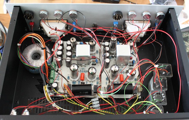
Well, it seems there is more to it than a lifted junction on the PCB... let's take this slow in a timeline
-- I first made this board to use with molex-like connectors
-- then since I had to wait so much time for molex tool and case front panel, I wired one channel directly, just to hear how it sounds
-- I enjoyed that channel for some time, until finally the case and tools arrived
-- I stripped the wires out and that killed one of the output transformer pads next to the relay - marked PNK
-- I pupulated the other channel and placed molexes into previously populated channel, making sure the lifted pad was soldered to the molex receiver before I soldered the other pins
-- On power up the new (previously unpopulated) channel works and the old one doesn't - the output is very highpassed
-- I trace this around, at it seems the signal is healthy after the 10uF solen
-- hooking up the trafo directly to the 10uF output + gnd and getting that to XLR produces a nice, clean signal, however since the VU connection is bypassed, but I have no VU movement for output (and I need that)
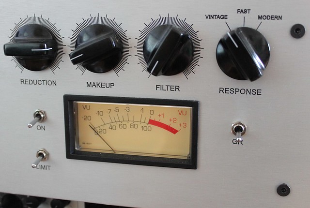
-- so I remove the molex completely and solder the trafo outs to the lower pads of the output relay (which are linked to the VU by the PCB and to the XLR out with the relay)
-- the sound is still highpassed (?!?!?!?)
-- also, measuring resistance between pin2 of input and output on that channel gives me some resistance that rises as if measuring a capacitor in circuit and that doesn't happen on the healthy channel
any ideas?? I've tried a lot of things, maybe the input XLR is shorted to gnd somehwere? Or the input trafo?