D-LA2A Support Thread

GroupDIY Audio Forum

Help Support GroupDIY Audio Forum:

This site may earn a commission from merchant affiliate links, including eBay, Amazon, and others.
Cool I'll try replacing the NEONs with Zeners tomorrow.

BTW, does anyone have a pinout for the T4B (-socket)? I would like to do some continuity testing with the valves and T4B removed, to find my GR metering problem.
 
Randyman... said:
Also - On the Neons - Is it generally recommended to replace them with the Zeners mentioned above?  Will a zener really make these units quieter and more reliable?

Yes and yes. There was in depth discussion in another thread. You can still find it with the correct keywords. I seem to recall SSLTech (keith) wrote about it a lot.
 
Kingston said:
Randyman... said:
Also - On the Neons - Is it generally recommended to replace them with the Zeners mentioned above?  Will a zener really make these units quieter and more reliable?

Yes and yes. There was in depth discussion in another thread. You can still find it with the correct keywords. I seem to recall SSLTech (keith) wrote about it a lot.

Disagree ;D
My D-LA2A is dead quiet with Neons
 
Well, for better or worse, I just swapped it to Zeners and now my unit is making zapping noises on power up  :mad:
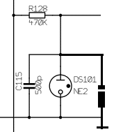
I am not sure if I have the orientation right... is it supposed to be like this (obviously with the Neons removed):
ZenerOrientation.gif
 
[silent:arts] said:
Disagree ;D
My D-LA2A is dead quiet with Neons

Noise is simply not there with the zener as a shunt regulator, while a neon can be considered a noise generator. You might get lucky and not have the neon interfere in a particular build. The most important part in the use of zener here is reliability. It will last "forever" and the regulation will not change over time. No need to readjust metering. Neons are light bulbs and inside the LA2A in a particularly hot furnace. They might have more limited life span than even the tubes!  :eek:

With this information at hand, why would anyone ever use a neon regulator anymore? It's not like it's responsible for the LA2A sound in any way or somehow visible in a finished build.

briomusic said:
Well, for better or worse, I just swapped it to Zeners and now my unit is making zapping noises on power up  :mad:
I am not sure if I have the orientation right... is it supposed to be like this (obviously with the Neons removed):
ZenerOrientation.gif

Yes, that's the correct orientation. http://en.wikipedia.org/wiki/Linear_regulator

I've never heard these zapping noises. The zener is not even in the audio path, so it might be something else.
 
The Zapping noise was coming from the PCB, no audio outputs are connected at this point, in fact not even the tubes or T4Bs. That's why I thought I might have the Zeners upside down maybe creating a "mini-short". I am gonna download the datasheet just to be sure.....

ETA: Triple checked Zener Orientation - still zapping/frying noise, gonna sleep over it and might put Neons back in tomorrow  :-\
 
Ok, Neons in again and we're back in business - audio and Kompression Happening As normal. Right Meter showing gain reduction BUT the needle is movin UP from zero as compression is applied. Wtf?
Any help appreciated!
 
briomusic said:
Ok, Neons in again and we're back in business - audio and Kompression Happening As normal. Right Meter showing gain reduction BUT the needle is movin UP from zero as compression is applied. Wtf?
Any help appreciated!

Did you change anything besides the neon? I have the same issue you originally had (no GR metering) in my single LA2A. I've always thought it to be a faulty TB4. I only have one so I can't swap TB4s around. Not a big deal as I just use my ears, but it would be nice to get it right anyway.
 
I solved it this afternoon  ;D

Problem was that the trimmer I am using instead of Rx25 was not connected (to ground) on one side. This lead to crazy voltages around the meter, I am glad I didn't damage it in the process.  :eek:

Now everything is working, and I am just working out what I am going to do about the (1M) Limiter Response Trimmer. Currently I have replaced it with a Lorlin Rotary which lets me switch between 0-960k in 120k increments. I am planning to have all the controls on (rotary) switches eventually, for the sake of recallability.

Once this is all sorted I can finally order a frontpanel - and then finally get my own DLA2A banner  :D
 
I'm a bit confused by the US-BOM from azone:

1. It lists 3x SPSD switches and 3x DPDT switches. I guess one of the additionals is the Link/Dual switch, but what is the other one for? ???

2. It lists DPDT switches with ON - NONE - ON while the Drip manual says they won't work and ON - ON switches should be used.

3. It lists SPSD (ON - NONE - ON) insead of SPST (OFF - ON). For what is the additional ON position or am I missing something?

I'm using that one because the other BOM doesn't even list the switches and I'm ordering parts from Mouser anyway.

 
This kinda fooled me too, but then i realized someone may have set up the switches their own way....etc.

Easiest thing to do was to have a look at the wiring diagram and see how things are working, then figure what you need from there.
http://www.groupdiy.com/index.php?topic=32677.msg503869#msg503869

Limit/comp is a spdt switch, with comp in the closed position.
In/out is simply switching 5v to your relay's.
Gr/level is a dpdt switching between gr and vu for meter.
Link/dual is spdt with one wire only.
 
Today i solved the Hummmmmmm problem
the problem was the connection between XLR ground (pin 1) to the case chassis
Now all is working good
Thank you All
Fabio


Audioman said:
Hi All,
For the distortion problem solved (wiring problem on ch 1)
but on both unit the hum is still present (on first unit on ch1 on second unit on ch2)
i have measure on first unit 55° degrees on the electrolytic c171 is it normal ??
Any idea ??


[silent:arts] said:
desol: first remove the power switch from the middle of the case.
running 115V / 230V next to the potentiometer / switch wires is a very bad idea in this build.

Audioman, nice build with unique front panels :)
Audioman said:
1- in my unit is some hum on the second channel when i switch on the channel (with the in/bypass switch)
2- the first channel of my unit works fine but if i bypass the channel in the audio a boom appears (maybe the switch is not good..)
the switch only triggers the relay. any DC at the output?
Audioman said:
3- in the second unit a strange distortion appears if i push the input and ouuput stage
try swapping the tubes from unit 1 & 2. any changes?

Cyrill: congrats!
interesting 1178 front panel layout.
COOL  8) 8) 8)
 
Hi to all !

I'm follow your great guide to make my own D-LA2A but i'm using 2 sowter 4383f for input and 2 sowter 8940a for output, my question is: the wiring for this is the same like the edcore ?

INPUT edcor XSM 600/10k
edcor pin 1 = 4383 brown
edcor pin 2 = 4383 pink
edcor pin 4 = 4383 green
edcor pin 5 = 4383 blue
edcor pin 8 = 4383 grey
edcor ground= 4383 black

OUTPUT edcor XSM10k/600
edcor pin 1 = 8940 yellow
edcor pin 4 = 8940 green
edcor pin 5 = 8940 grey
edcor pin 8 = 8940 pink
edcor ground= 8940 black

Also , someone can please put some pic of the connections of the AC input wiring and the jumper and c8 ( i'm confused whit this  ??? )  ?

Again thanks !!!!!
 
HI all of you!

I have a question.. I am close to finish the pcb building but i can't  find information about:

1. how to wire the rondo muller psu,I can't understand what is the function of the three black wires in volker's picture  neither the connection of the on off toggle switch ( in the pcb i can notice that it have only two pins)


2.  what is the small box  next to the power connector?


3.  how to wire the sowter transformers and the switches on-on  with the  six and three  ends? (terminals)


for the sowters can i use the same edcor's configuration ?

INPUT edcor XSM 600/10k
edcor pin 1 = 4383 brown
edcor pin 2 = 4383 pink
edcor pin 4 = 4383 green
edcor pin 5 = 4383 blue
edcor pin 8 = 4383 grey
edcor ground= 4383 black
OUTPUT edcor XSM10k/600
edcor pin 1 = 8940 yellow
edcor pin 4 = 8940 green
edcor pin 5 = 8940 grey
edcor pin 8 = 8940 pink
edcor ground= 8940 black


Thanks for your help.
 
Back
Top