You are using an out of date browser. It may not display this or other websites correctly.
You should upgrade or use an alternative browser.
You should upgrade or use an alternative browser.
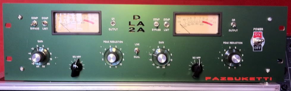
D-LA2A Support Thread
- Thread starter [silent:arts]
- Start date


Help Support GroupDIY Audio Forum:
This site may earn a commission from merchant affiliate
links, including eBay, Amazon, and others.
[silent:arts]
Well-known member
look at the picture in the pdf sonicwarrior posted above.mativas said:1. how to wire the rondo muller psu,I can't understand what is the function of the three black wires in volker's picture neither the connection of the on off toggle switch ( in the pcb i can notice that it have only two pins)
the PSU transformer only has 2 black wires, which are one of the two heater secondaries.
there is no main power on the PCB, you wire the on/off switch between the IEC connector and the PSU transformer primaries.
it is a 120V/220V switchmativas said:2. what is the small box next to the power connector?
for the sowter transformer use the color code printed on the PCB.mativas said:3. how to wire the sowter transformers and the switches on-on with the six and three ends? (terminals)
for the switch wiring use the sonicwarrior pdf (thanks btw)
sea_man
Member
Thanks for your reply , the sowter and all the switch ( except the on/off) are ready !!!
The only part i can't understand now is the AC input for rondo power transformer ( PSU transformer primaries)... this have 4 cables in pairs whit black thermo-retractable ( one wire yellow and other white inside) each .. and i see in many pics two of this wires connected together and in others not..
Can you please guide me to connect this to the IEC connector and the on/off switch ?
Also , i left today to buy the cap for C8.. but this comes in different voltages.. which is the correct ?? 0.1uf wima ***v??
Thanks !!
[silent:arts]
Well-known member
well, for 110V mains those 4 wires are parallel, for 220V seriellsea_man said:The only part i can't understand now is the AC input for rondo power transformer ( PSU transformer primaries)... this have 4 cables in pairs whit black thermo-retractable ( one wire yellow and other white inside) each .. and i see in many pics two of this wires connected together and in others not..
rob_gould
Well-known member
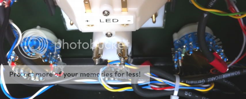
I'm interested in adding LED meters to this project.
This subject doesn't seem to have come up since most people go for analogue meters for their builds, more in keeping with the classic look.
Is it possible to add LED meters to an LA2A circuit?
Would something like this be of any use?
http://www.groupdiy.com/index.php?topic=23977
Cheers,
Rob
This subject doesn't seem to have come up since most people go for analogue meters for their builds, more in keeping with the classic look.
Is it possible to add LED meters to an LA2A circuit?
Would something like this be of any use?
http://www.groupdiy.com/index.php?topic=23977
Cheers,
Rob
sea_man
Member
[silent:arts] said:well, for 110V mains those 4 wires are parallel, for 220V seriellsea_man said:The only part i can't understand now is the AC input for rondo power transformer ( PSU transformer primaries)... this have 4 cables in pairs whit black thermo-retractable ( one wire yellow and other white inside) each .. and i see in many pics two of this wires connected together and in others not..
Thanks ! it work fine.
For now i need wire all cables again whit shield.. i forgot this ;D .. because this i have a lot of noise...
Also i will make a pics tomorrow for the forum .
Again.. thanks for your help , it is my firs tube project !


sea_man
Member
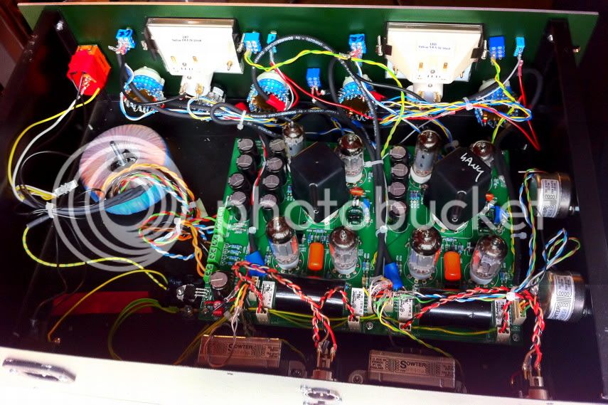
I finish my project ! 8)
Here are the pics:
http://www.flickr.com/photos/mar1o_bross/sets/72157627001849463/
Thanks for your help !
Here are the pics:
http://www.flickr.com/photos/mar1o_bross/sets/72157627001849463/
Thanks for your help !
[silent:arts]
Well-known member
sea_man said:I finish my project ! 8)
congrats! nice work, and you are still allive 8) 8) 8)

sea_man
Member
Thanks !
The only problem i have now is a hum sound in the right channel
can you give me any advice?
The only problem i have now is a hum sound in the right channel
can you give me any advice?
sea_man
Member
Hum sound is solved swapping the tubes and wiring better the front and the rondo ! ( your advice ") )
)
Now is working fine !
Thanks for all your help and for the signature/banner !
)Now is working fine !
Thanks for all your help and for the signature/banner !
briomusic
Well-known member
finally finished my stepped-switch D-LA2A, and ready to collect my banner ;D
frontpanel by NRG CNC, almost made my way through all of frank's anodized colors now.
I should add: little scratches happened during assembly not at NRG.
pcb and power transformer by silent:arts, T4B by Drip, meters by Hairball
thanks to the posters in these threads for helping with the stepped switches:
http://www.groupdiy.com/index.php?topic=44553.msg558003#msg558003
http://www.groupdiy.com/index.php?topic=44800.msg561075#msg561075
I went for a custom spacing on the input gain: 1dB steps from -9 to +8dB, then 5dB steps from +10 to +35dB.
the uraltone type switches i got from ebay actually have 24 positions.
Additionally, I used a lorlin with 8 steps for the HF response trimmer. I will see over time if that's enough....
[silent:arts]
Well-known member
Brio, I nearly missed your D-LA2A - I'm sorry ...
Need a stepped switched version too 8)

Need a stepped switched version too 8)
briomusic
Well-known member
[silent:arts] said:Brio, I nearly missed your D-LA2A - I'm sorry ...
Need a stepped switched version too 8)
Thanks for the banner
This guy on ebay does 24step switches now, and even pre-resistor-soldered as log pot replacement:
http://cgi.ebay.de/2P-24-Step-Attenuator-Volume-Control-Pot-Log-100K-Mono-/260806367240?pt=LH_DefaultDomain_0&hash=item3cb9455808
briomusic nice build, 8)
Are those 24p switches ready to go, any circuit mods to be aware of? Thanks
Are those 24p switches ready to go, any circuit mods to be aware of? Thanks
briomusic
Well-known member
MicDaddy said:briomusic nice build, 8)
Are those 24p switches ready to go, any circuit mods to be aware of? Thanks
Thanks!
You could get the 100k log pre-configured switches as a drop in replacement for the 100k log pots (gain and peak reduction). I wanted a different scale for the gain, so I made up my own with higher resolution around unity gain and bigger steps towards the higher gain settings.
Hello everybody!
I need a little bit help with this one....
The thing is: My D-LA2A has been working wonderfully for something like 8 months now, everyday. Then, suddenly today the other channel stopped working.
Like this, it passes audio when I turn the gain, normally. But when I turn the Peak Reduction pot CW, instead of more compression, it works like reversed gain pot: sound disappears. And when it's fully CW nothing comes out.
I tried changing all the tubes and switching the T4B's no change. All tubes and the T4b's work in the other channel.
So, any ideas where to start looking?
BTW, the broken channel compresses and works normally when the Peak Reduction pot is fully CCW and Stereo Link is switched on and the control voltage comes from the working channel.
[silent:arts]
Well-known member
telefunk said:...
BTW, the broken channel compresses and works normally when the Peak Reduction pot is fully CCW and Stereo Link is switched on and the control voltage comes from the working channel.
which leads us to the potentiometer and its connections to the PCB, isn't it.
or maybe something around VX03 ...
benlindell
Well-known member
Just got my first one up and running. I had trouble finding info on the 25K +75K mod for gain, I put the 75K between the wiper and pin 2 on the molex. Should I have put it between pin 3 and the pot?
Also I have one channel working perfect and the other with just low thin sound, pretty sure it's the gain pot being not right so one thing at a time
Also I have one channel working perfect and the other with just low thin sound, pretty sure it's the gain pot being not right so one thing at a time