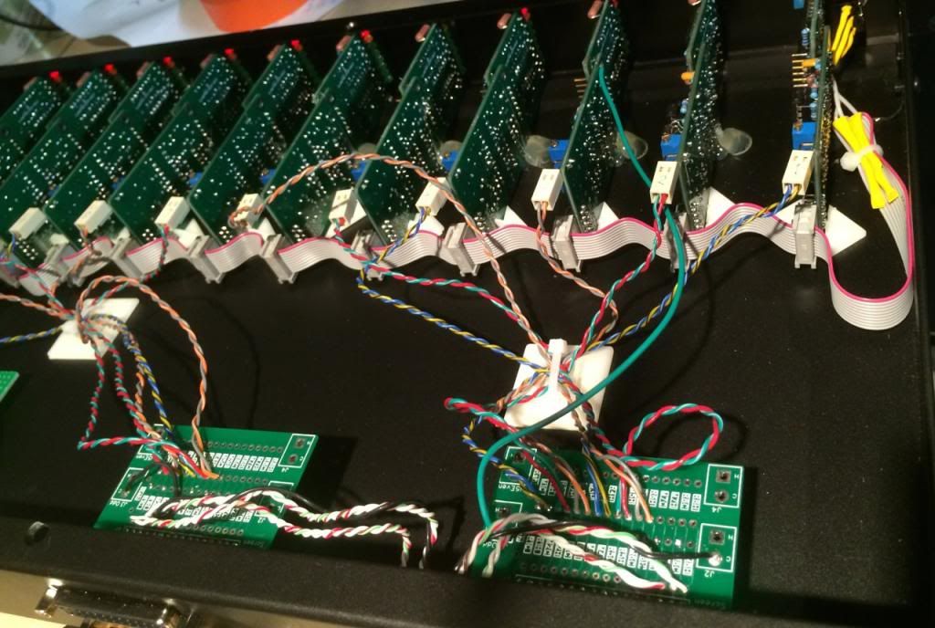
DB25 summing PCB - MK2??

GroupDIY Audio Forum

Help Support GroupDIY Audio Forum:

This site may earn a commission from merchant affiliate links, including eBay, Amazon, and others.
ruffrecords said:
It looks like I am just about to sell the last of the second batch of db25 boards. The first batch of 50 I made in May last year sold out right away. The second batch of 50 I had made in June of last year and has lasted 9 months. I am happy to make one more batch if there is sufficient interest. I am not asking for orders, just expressions of maybe I might need a couple in the next year sort of thing.

Cheers

Ian

I'd love 2-4 as well
How do I contact you for purchase?
 
PassiveActive said:
ruffrecords said:
It looks like I am just about to sell the last of the second batch of db25 boards. The first batch of 50 I made in May last year sold out right away. The second batch of 50 I had made in June of last year and has lasted 9 months. I am happy to make one more batch if there is sufficient interest. I am not asking for orders, just expressions of maybe I might need a couple in the next year sort of thing.

Cheers

Ian


I'd love 2-4 as well
How do I contact you for purchase?

Looks like there is sufficient demand to warrant another batch of 50. I will place the order today. Should arrive in a couple of weeks.

To order go here and follow the instructions:

http://www.ianbell.ukfsn.org/EzTubeMixer/

Cheers

Ian

Edit: Boards due on 4th April
 
ruffrecords said:
PassiveActive said:
ruffrecords said:
It looks like I am just about to sell the last of the second batch of db25 boards. The first batch of 50 I made in May last year sold out right away. The second batch of 50 I had made in June of last year and has lasted 9 months. I am happy to make one more batch if there is sufficient interest. I am not asking for orders, just expressions of maybe I might need a couple in the next year sort of thing.

Cheers

Ian


I'd love 2-4 as well
How do I contact you for purchase?

Looks like there is sufficient demand to warrant another batch of 50. I will place the order today. Should arrive in a couple of weeks.

To order go here and follow the instructions:

http://www.ianbell.ukfsn.org/EzTubeMixer/

Cheers

Ian

Edit: Boards due on 4th April

I sent you an email

Looking forward to corresponding =)
 
Down to just 3 left.

If anyone thinks they are likely to need one or meore in the next few months let me know and I will order another batch.

Cheers

Ian
 
Hello!

I am assembling a small passive box with one of Ian's PCBs, and I hoped I someone here could check out my math before I start putting it together. :)

I want to build a board with 2 mono channels and 3 pairs of left and right (standard) channels.

As suggested in Ian's helpful documentation, I'm using 4k7 resistors on standard channels (Rin(s)=9k6) and 6k8 on mono channels (Rin(eff)=6k8). My guess is that the bus resistance should follow from the formula

1/Rbus = Nm/Rin(eff) + Ns/Rin(s),

where Nm = 2 (number of mono channels on a bus), Ns = 3 (number of standard channels on a bus), which in my case would yield

Rbus = 1/(Nm/Rin(eff) + Ns/Rin(s)) = 1/(2/6k8+3/9k6) = 1630 ohms.

If I want a source resistance of 200 ohms, I think I should choose Rsh to be

Rsh = 1630*200/(1630-200) = 228.

Do these computations look ok? :)
Also, is there a simple way to calculate the bus loss for this configuration?

Thank you in advance for your help!
 
Ian:

Is someone eating the cards?  (PCB Potato chips).  You have shipped about 140 of them. I have seen pictures of 4 projects (*2 of mine!).

Lets see some project pictures folks!

I have done two projects, one is a "Summer" I called SUM THING (apparently that name is taken multiple times, sorry) and I posted Pic's on this thread.  The other I used them as an easy way to connect D-Sub 25 pin connectors to internal wiring).  Here is a picture and a link to it's thread.

Built a little GDIY 51x meter bridge (1U rack, 11 meters, each meter positioned directly over the corresponding module).  I used your modules to connect them.

VU8-3_zps93831984.jpg


Writeup:

http://groupdiy.com/index.php?topic=53957.msg711299#msg711299

PS

Ian.  A change suggestion.  If you do make another set sometimes, I would suggest separating the grounding.  TASCAM allows for multiple grounds (for each shielded balanced pair), but the nature of the way the card is set up does not allow the separation of those grounds.  Your cards solder them all to the ground plane, which is connected to chassis, and to the DB25 shell. Instead Perhaps you could run a ground trace from pin to a pad followed by a trace we could cut to the ground plane, so there would be a place to cut it with a knife or dremel. 

It hasn't mattered much in my projects yet because:
1) The original GDIY 51x racks do the same thing on the 50 pin connectors which I use on my TASCAM DB25 mod cards.  All grounds are connected on the 50 pin connectors. 

2) Because on the meter project I don't reference the ground at all.  They all have balanced line receivers.  However it would be nice (without it, it was tricky to deal with the virtual ground on the meter rack so I could use a single supply.  Still not sure that is working perfectly.)

just a suggestion.

(Anyway very curious about where all these cards are going.  I have used all mine now.  It reminds me of that Tom Waits song... "What's he building down there!")

Best

Bruce
 
Lagrange said:
Hello!

I am assembling a small passive box with one of Ian's PCBs, and I hoped I someone here could check out my math before I start putting it together. :)

I want to build a board with 2 mono channels and 3 pairs of left and right (standard) channels.

As suggested in Ian's helpful documentation, I'm using 4k7 resistors on standard channels (Rin(s)=9k6) and 6k8 on mono channels (Rin(eff)=6k8). My guess is that the bus resistance should follow from the formula

1/Rbus = Nm/Rin(eff) + Ns/Rin(s),

where Nm = 2 (number of mono channels on a bus), Ns = 3 (number of standard channels on a bus), which in my case would yield

Rbus = 1/(Nm/Rin(eff) + Ns/Rin(s)) = 1/(2/6k8+3/9k6) = 1630 ohms.

If I want a source resistance of 200 ohms, I think I should choose Rsh to be

Rsh = 1630*200/(1630-200) = 228.

Do these computations look ok? :)
Also, is there a simple way to calculate the bus loss for this configuration?

Thank you in advance for your help!

Your math for the stereo channels is OK. For the mono channels you have to treat each bus separately so Rin = Rhot + Rcold = 13K6. The bus inputs are then connected together so to the outside world the input impedance becomes Rin/2.

If you add a shunt resistor to make the bus impedance eqault to 200 ohms then the bus loss calculation is simple - it  is just Rin/200. So for your stereo inputs it is:

(4700 + 4700)/200 =47 = 33.44dB.

You would expect the bus loss for the mono channels to be 3dB more. Again the bus loss is just Rin/200 which is:

(6800 +6800)/200 = 68 = 36.65dB

Cheers

Ian
 
bruce0 said:
Ian:

Is someone eating the cards?  (PCB Potato chips).  You have shipped about 140 of them. I have seen pictures of 4 projects (*2 of mine!).

Lets see some project pictures folks!

I don't know what they are all being used for. I get quite a lot of orders for 2 or 3 so I guess there are quite a few 16 and 24 track summers being built. However, in the last batch I had one order for 6 boards and another for 12!

Ian.  A change suggestion.  If you do make another set sometimes, I would suggest separating the grounding.  TASCAM allows for multiple grounds (for each shielded balanced pair), but the nature of the way the card is set up does not allow the separation of those grounds.  Your cards solder them all to the ground plane, which is connected to chassis, and to the DB25 shell. Instead Perhaps you could run a ground trace from pin to a pad followed by a trace we could cut to the ground plane, so there would be a place to cut it with a knife or dremel. 

just a suggestion.

Bruce

I am not sure about this. They are not really grounds, they are screens ( they don't carry signal current) and they should all be connected directly to the chassis close to the input. It is just like the XLR pin 1 problem but 8 times over on one connector. Having said that I will have a look at the PCB to see if it is possible to make it a simple mod.

Cheers

Ian
 
ruffrecords said:
I am not sure about this. They are not really grounds, they are screens ( they don't carry signal current) and they should all be connected directly to the chassis close to the input. It is just like the XLR pin 1 problem but 8 times over on one connector. Having said that I will have a look at the PCB to see if it is possible to make it a simple mod.

Cheers

Ian

Thanks Ian.

Good point.

But on a summer, with a single unbalanced input, the unbalanced signal will contain all the noise from all shields (and the outboard cases they connect to).  So I think it "Could" become problematic.

But I agree with you they are shields, and hypothetical needs are not good product requirements. 
I almost always use balanced connections, so I can't say I need it. 
And as I say, my GDIY51X TASCAM connections do exactly the same thing (no choice in my situation because the backplane did it for me).

But I noticed it (I was "attuned" to the issue after struggling with the same issue on the GDIY51X backplane), and since it might be easy to change, i thought I would mention it.

Bruce
 
Hi Bruce,

I had not considered a single unbalanced input - but if you have such a thing then it would be best to balance it with a transformer before feeding it to a balanced summer. The cost of a transformer is a small price to pay for saving hours of grief. I am not sure separating the shields out would help all that much because, eventually that unbalanced screen will get connected to one arm of a balanced input and insert the noise. But, as I said, I will have a look at it.

Cheers

Ian
 
ruffrecords said:
Your math for the stereo channels is OK. For the mono channels you have to treat each bus separately so Rin = Rhot + Rcold = 13K6. The bus inputs are then connected together so to the outside world the input impedance becomes Rin/2.

Great, thanks for the correction!
Being somewhat of a novice in DIY electronics, I'm still not 100% sure how to calculate an exact value for the shunt resistor (my guess is that I should change 6k8 to 13k6 in my formula). But I can see that since the bus resistance will anyway be much larger than 200, the required shunt resistor will always be just a little bit over the target value for the bus impedance. Also, a smaller shunt resistor value will yield a smaller bus impedance. Based on this, I think some 210-220 ohms will be close enough. :)

I really like the board, simple and effective. :)
 
Lagrange said:
ruffrecords said:
Your math for the stereo channels is OK. For the mono channels you have to treat each bus separately so Rin = Rhot + Rcold = 13K6. The bus inputs are then connected together so to the outside world the input impedance becomes Rin/2.

Great, thanks for the correction!
Being somewhat of a novice in DIY electronics, I'm still not 100% sure how to calculate an exact value for the shunt resistor (my guess is that I should change 6k8 to 13k6 in my formula). But I can see that since the bus resistance will anyway be much larger than 200, the required shunt resistor will always be just a little bit over the target value for the bus impedance. Also, a smaller shunt resistor value will yield a smaller bus impedance. Based on this, I think some 210-220 ohms will be close enough. :)

I really like the board, simple and effective. :)

With just 8 channels, you are quite right, the bus impedance is always way over the wanted 200 ohms so a slugging resistor in the 200 to 220 ohms range will usually be required. You have probably realised that the bus loss is also always pretty much the same.

Glad you like the design of the boards. By the way, that's what my wife calls me, simple and effective!!

Cheers

ian
 
Are you sure you are hearing that second word correctly? :)  It can be hard to hear the two d's, at least when spoken by an american it can be.
 
ruffrecords said:
Glad you like the design of the boards. By the way, that's what my wife calls me, simple and effective!!

Nothing wrong with that! :D
Certainly better than for example "complicated and useless"... ;)
 
As you probably know, the DB25 board is intentionally pretty simple. I resisted requests to add pan and aux controls and kept it simple. Well, the inevitable has happened, someone has contacted me directly about adding a pan control to a mono channel.

Adding something other than a simple L-C-R pan switch al la New York Dave is non-trivial. So I have come up with a simple scheme that should work. It uses the 'Neve Trick' we used to make simple balanced monitor level controls with a single pot but extended to turn it into a pan pot. It relies on the bus being connected to a transformer rather than an electronically balanced input. The schematic is attached. The guy who first asked for it has built one and it works which is why I am now posting it to the group.

To implement it you need to connect to the hot and cold inputs of the channel from J7 to the pan pot circuit. R3 and R5 connect the bus directly to the channel cold input so you can fit them as normal to the PCB (R1C and M1C for example). R4 and R6 can have their bus end connected to the DB25 board (R1H and M1H for example) and flying lead taken to the pan pot sliders.

Cheers

Ian
 

Attachments

  • BalancedPan.png
    BalancedPan.png
    14.5 KB
dmp said:
Ian,
What do you think of the single pot pan like this:

To do a proper balanced pan pot you really need four pots. The 'Neve Trick' is a compromise that works with transformers and allows only two pots to be used. It should not be confused with a regular unbalanced pan pot that uses two pots. Regular unbalanced two pot pan pots can be replaced by the single pot unbalanced pan in your schematic but neither is appropriate for used as a balanced pan pot.

Hope that makes sense.

Cheers

ian
 

Latest posts

Back
Top