dbx 160vu clone

GroupDIY Audio Forum

Help Support GroupDIY Audio Forum:

This site may earn a commission from merchant affiliate links, including eBay, Amazon, and others.
Rob Flinn said:
use Green A & Blue B for the centre tap & connect to the middle pin marked G on the board, & the other green B & blue A indiviudally to the points marked A on the board either side of the point marked G

Hi Rob,

Thank you again - I'll give that a try and post back later tonight.

DY
 
j.frad said:
We have original 160VUs here, if you have drums, basses and vocals, I can run them through.
The behavior is most noticeable on kick, snare, voices.
jules.

Awesome Jules!
www.acsoundstudio.com/DIY/160vu/TEST/808_TEST.wav
www.acsoundstudio.com/DIY/160vu/TEST/BASS_TEST.wav
www.acsoundstudio.com/DIY/160vu/TEST/DRUMS_TEST.wav
www.acsoundstudio.com/DIY/160vu/TEST/VOX_TEST.wav

The first go on each of those files is uncompressed....followed by compression.
 
Rob Flinn said:
use Green A & Blue B for the centre tap & connect to the middle pin marked G on the board, & the other green B & blue A indiviudally to the points marked A on the board either side of the point marked G
SUCCESS!!!  Thank you Abe & Rob!  I had to swap the secondary leads.

Voltages on the Alt PS Pads:

Pad 1: -31.9
Pad 2: *ground*
Pad 3: +30.9
Pad 4: -34.4
Pad 5: +32.9

Thanks again, Fellas!

Now, I'm going to install the rest of the ICs and see if these VCA & RMS cans will pass audio...

DY
 
Rob Flinn said:
Glad this helped.

I must say I think it's rather poor that the transformer manufacturer uses the same colour wires for both the 2 primaries & the same colours on  2 secondaries.  I don't think I've seen this before, & it's obviously open to misinterpretation.

Rob,

I had to admit: having same color/colour wires on primaries and the secondaries was a cheap education to get me to do resistance/AC checks and what can happen if I pair up the wrong secondaries.  I will never, ever forget if there is a positive ohm reading while testing two secondary leads, then those leads are NOT to be paired up for a centertap.  ;D
 
The PSU voltages still aren't correct. I yanked the molex AC In pin and hardwired the leads in to the pcb:

Pad 1: -43.7V (should be -15V)
Pad 2: *ground*
Pad 3: +20V (should be +15V)
Pad 4: -45V (should be -24V)
Pad 5: +22 (should be +24V)

I have no idea whyThe diodes still read 25V across each one and on to the first filter cap (C36), it reads -48V where it should read -24V according to the schematic.  I think those secondary leads are still wired wrong and every other combination pf blue/green blows fuses.

I've triple checked for solder blobs, component orientation, performed continuity testing above/below pcb, performed trace routings from diodes to filter caps/16V 22uF caps to the PS pads.  This PSU should work.  After 5 nights of not being able to get a simple centertapped power supply running, I'm going to take a break from this and start on something else.  It's probably something simple I'm overlooking and when I come back to it, hopefully I'll go, "duh...!"

Thanks All!

DY
 
Hi Rob,

I have a Triplett 9005A DMM and yes, it has a diode test function on it.  I just noticed the little bugger even has an hfe function on it too.  Never used either function but it sounds like I'm going to learn how to test diodes.

I think I see where you're going with this.  Since the voltage is doubled on one rail, one of those diodes (which are supposed to block electrons from crossing jumping over to the other rail) may be inserted backwards (allowing voltage to jump from one rail to the other) or is malfunctioning altogether.  I've already checked to ensure they are oriented correctly and I confirmed this with continuity testing.  I've checked to ensure 25V is running across each diode.  Is there something else I should check?

Thank you in advance!  I appreciate the help...this PS is driving me batty!

DY
 
switch your meter to diode test, & put the probes across a diode, it should read around 0.6.  If it doesn't hook the probes up to the diode the other way round.  i.e reverse the polarity.  If it doesn't measure around 0.6 in either direction replace the diode.  Move on to the next diode..... etc
You don't need to take the diodes off the pcb to do this.
 
Rob,

Here's my diode tester results with both lead orientations:

D16 = "1", 538
D13 = "1", 541
D14 = "1", 541
D15 = "1", 538

Is that any help to you?

Thank you in advance,

DY
 
They sound reasonable readings
.
I've never used the chips in the PSU myself before & not actually having the boards here, it's a bit difficult for me to take this much further.  You probably need someone else to chime in who has built one.  Failing that I should have some boards in a few weeks so I'll probably be asking you questions by then !
 
Tossed in the other LM301 and no change.  Still around 48V.

While I was checking diodes in diode mode:

D18 (1N9608) = "1", beeps continuous
D19 (1N4383) = "1", "-1" (no beep)

Could D19 be the culprit?

DY

 
is this the latest/greatest bom?

abechap024 said:
Hi all,
I don't want to be jumping back and forth from the order thread so I'll post all updates here. Also I've taken the liberty of naming this the "CLX" which happens to be the roman numeral for 160 (thank you wikipedia!)

BOM for respective sections, will update a BOM for the full build:

Recommened  ;D ;D ;D:
FULL Build

Section BOMs:
Main Board for Build
Original 160vu Power supply
RMS detector
Discrete / that VCA


updated schematic and PCB overlay (hopefully easier to read)

Just Main Board Schematic
Full Schematic
Reference PCB Layout


btw sorry the schematics are so funky - I've been fighting this program ever since I converted it from eagle...So bear with me...
Cheers!
AC

ps. found out today boards will be shipped from factory on the 17th
 
Haha Kind of! Will be uploading latest and greatest BOM! Updated power supply and Res Defs to match the original schematic.
Thanks for asking that.
Abe
 
Rob Flinn said:
both sound suspect.  The 1n9608 is a zener diode, but you should still measure the forward V drop.

Hi Rob,

Yanked both diodes, and they test fine.

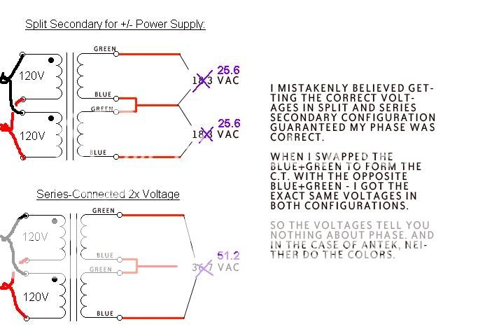
Here on this board, I found another user of Antek using the same toroidal for his 1176 clone.  He too, was having issues of one of the rails having double the voltage.  He posted the following comment with comments on an image (see link below; please note I put my readings are in purple).  

Kato writes:
I return to this thread with some disappointing news.
After blowing a few more fuses this weekend, I discovered that correct voltages in parallel and split secondary do not guarantee a correct phase relationship. I'm not sure how I got that idea.

Here's the image, his comments on the image, with my readings in purple:

powersupplyissue.jpg


So my question is: is my power supply for this clone good to go?  

Thank you in advance for your expertise!

DY
 
Back
Top