abechap024
Well-known member
Yes. 25v (preferably ~20-24ish but 25 will work fine) Those voltage readings are exactly in the ballpark on what is needed to run this board.
Abe
Abe


Hmmm...this is how I have it wired. But when I check the pads on the Alt PS to ground, I get:abechap024 said:Yes. 25v (preferably ~20-24ish but 25 will work fine) Those voltage readings are exactly in the ballpark on what is needed to run this board.
Abe
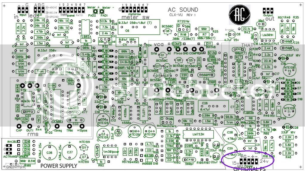
Here ya go, Rob - it's the purple oval down at the lower right hand side of the board. Does this help?Rob Flinn said:Unfortunately since I don't have the board myself, I don't even know what pad 1 to 5 are, so it's difficult for me to help you further at the moment.
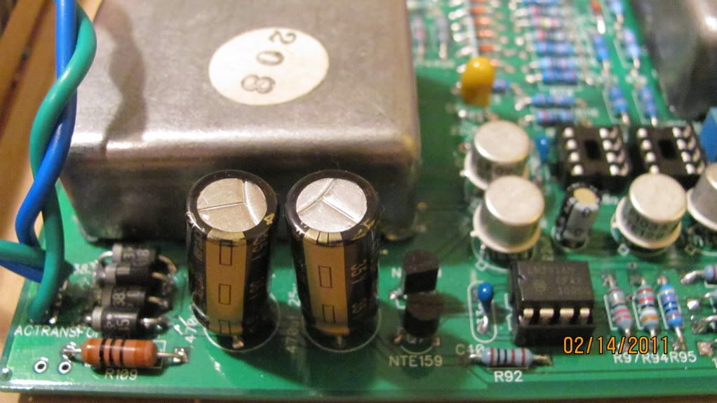
damnyankee said:I'm thinking I should not be using those pads for checking voltage.
Instead, I measured across the filter caps (C36, C37). C36 reads about 18V across it's terminals, C37 reads about 48V across its terminals.
From AC In to the diode bridge to the filter caps, are these voltages across the filter caps acceptable?


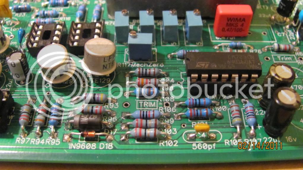
") . All in all the That chip is cheaper and sounds great. But the Discrete VCA seems like a fun challenge all in itself.
. All in all the That chip is cheaper and sounds great. But the Discrete VCA seems like a fun challenge all in itself.


![Soldering Iron Kit, 120W LED Digital Advanced Solder Iron Soldering Gun kit, 110V Welding Tools, Smart Temperature Control [356℉-932℉], Extra 5pcs Tips, Auto Sleep, Temp Calibration, Orange](https://m.media-amazon.com/images/I/51sFKu9SdeL._SL500_.jpg)


