Debugging my SSL 9K2 (api 200 board)

GroupDIY Audio Forum

Help Support GroupDIY Audio Forum:

This site may earn a commission from merchant affiliate links, including eBay, Amazon, and others.

gemini86

Well-known member
Joined
Sep 22, 2008
Messages
2,477
Location
Eugene, OR USA
Hey guys...

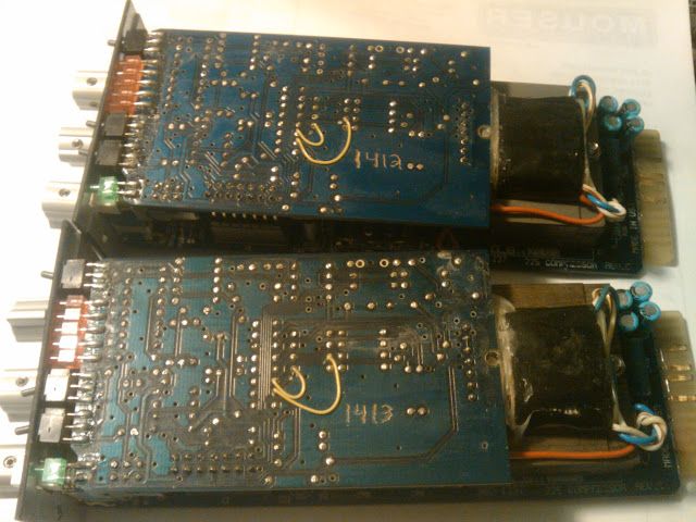
I'm trying to debug the 9K2 boards before I send them out to the forum.

Right now it passes audio, but distorted due to the huge oscillation at around 8.5 Khz and slightly smaller up at 17 Khz(I'm guessing just because of the distortion).

Here's what pin 1 of the TL072 looks like on a PC soundcard scope:


Attachments

  • pin1_tl072.JPG
    pin1_tl072.JPG
    160.8 KB
...full disclosure:

R81 and R 117 (50K) are 47K right now, forgot to order them with the lot, so I sub'd in what I had. Could that cause any problems?

Also, I'm using TL072 to run the whole preamp at +-16V. It was suggested I try TL052 per the original, or try TLE2082 which is supposed to be an upgrade to the TL05x,7x,8x lineup. I ordered a couple of each to try out.

I tried swapping for a TI TL082 that I had, but no change.

I'm paying interest on my CC for these, and it would be nice to get these out to the forum. I'm not the most skilled at diagnostics when it comes to AC systems (I'm only really formally trained on DC automotive systems, pretty dumb circuits). The oscillation appears a little bit throughout the whole preamp, but it's noticeably larger at the output of IC24 (output amp)

[pity party]Any help VERY much appreciated! (I'm awake at night thinking about this)  [/pity party]
 
Hello!

Ist this Schematic redrawn by you?
I dont know the original so i may be wrong but when i was just looking at the schem i saw that R115 and C86 are not connected to pin6 of IC30. For me it looks they form the Feedback-path but are connected to the compensation cap C74 and pin 8 of IC30 instead of the output of IC30. The same thing happens around IC23.
As i dont know the original Schematic this is just a guess!

regards,
Wolfgang
 
holy crap, man...

you spotted it.

The schemo doesn't show pin 6 connecting to the feedback loop, but kieth's diy PCB layout has r115, c86 connecting from pin 6 to pin2 of IC30.

same on ic23.

man do I feel like a jackassss... I figured it was just a topology that was over my head but it in in fact a schematic error.

simple trace cut and a jumper should fix it.

THANK YOU!
 
there seems to be quite a few changes from the original to the redraw that might need to be looked at.  I remember 3nity having some problems with his 500 version that required a few mods.  To me the entire first stage is where most of the changes occur.  And I'm not talking about the orientation of the IC's on the schematic but parts connected to places they shouldn't, as well as the omitting of a few resisters here and there.

I've attached the original below for comparison if folks don't have it.

-Casey


Attachments

  • SSL 9k mic pre.pdf
    539.3 KB
Hi Bruno I'm getting "page not found' when clicking on your schematic link.

bruno2000 said:
Here's the schematic I used.
http://www.dopplerstudios.com/pictures/SSL 9K-42Sch.pdf
Best,
Bruno2000
 
Does this means that ordered the boards with this mistake?
Did you fixed the problem on your proto?
Thanks.
 
Unfortunately all the boards have this mistake but I will cut the trace and mark where the jumper goes. Next time I'll be more patient and spend the extra cash on a proto run.
 
gemini86 said:
http://www.dopplerstudios.com/pictures/SSL%209K-42Sch.pdf

forum doesn't like spaces in links...

BTW bruno that is a great redraw, much easier to follow...

everything else looks right aside from the feedback loop mistake...

Just as a clarification, my schematic includes the feedback loop correction, as well as some additional power filtering options.
Best,
Bruno2000
 
Thanks again bruno, wolfgang, and everyone else who helped me out today!

No more oscillation, but I did have a weird gain control issue, which I finally tracked down to the pot being wired wrong. I had the second half of my gain control backward. These kind of bonehead mistakes I attribute to my lack of experience with this circuit. (it's the most complicated preamp I've worked on so far)

It is working well now. Ran some tests through RMAA, and the numbers look decent but I'm trying to wrap my head around the impedance mismatch. What pad values should I use to get the loading right on the input?
 
I'm happy to report that all bugs are worked out, and the unit is sounding VERY good.

It's happily running with a tl072 for dc servo, tl082 oscillates, haven't tried TLE2082 or tl052 yet.

I'll be doing the trace cuts as I send out boards and marking where jumpers should be placed after stuffing components. Only 3 jumpers are needed, and they're in easy spots.
If another run is produced, then I'll be correcting the mistakes for rev2.

in my defense, even the pros goof on PCB layouts, as evident by these API 225L modules :

IMG_20111201_202600.jpg
 
Back
Top