DESPERATION! No heater voltage on Stellar/Alctron tube mic power supply

GroupDIY Audio Forum

Help Support GroupDIY Audio Forum:

This site may earn a commission from merchant affiliate links, including eBay, Amazon, and others.
With the load connected, measure both sides of your 32 ohm resistor (R15?).  You have nearly 10V across the regulator under load, yet only 0.3V/22ohm = 14mA flowing through your test resistor.

Have you made any changes to the biasing diode that connects to the 'GND' pin of the 7806?  What if you bridge across it?
 
Dear fellas! I'm back with more info!!!

I've flipped the LM317 again, thanks for the hint with the pinout, that really slipped my vision. After the flip, I set the voltage again with the trim pot to 6.4 V, and then ventured to connect a load. Astonishingly the Voltage only dropped to 4V - wow, that's some progress. I then bridged R15 (32 Ohm - I checked again), turned it back on connected the load and measured full 6.4 VDC at the regulator output. YAYYYY!!!!! That felt so good.

So, what does it tell us? Well for one, that 32 Ohm is obviously too much. It also means that the 7806 must have been faulty, right? Anyway I'll reconnect the LM317 output wire to the PCB and see if I can measure the voltage at the 7-pin XLR as well (I only measure directly at the LM317 for now).

Important question: R15 was in there for a purpose, so what would be a sensible value for that one? I see you have had some discussions about this, I'm really curious what the "least common denominator" is that you would agree on!?

I've attached a picture to see the results for yourself. Here are some more measurement values:

No load attached (R15 in circuit):
Before Rect: 10VAC
LM317 In: 12.2VDC
LM317 Out: 6.4VDC

No load attached (R15 NOT in circuit):
Before Rect: 10VAC
LM317 In: 12.4VDC
LM317 Out: 6.4VDC

Load R attached (R15 in circuit):
Before Rect: 10VAC
LM317 In: 12VDC (approximately)
LM317 Out: 4.1VDC

Load R attached (R15 NOT in circuit):
Before Rect: 9VAC
LM317 Out: 6.4VDC
 

Attachments

  • Tested Working_cr.jpg
    Tested Working_cr.jpg
    1.2 MB
Matador said:
With the load connected, measure both sides of your 32 ohm resistor (R15?).  You have nearly 10V across the regulator under load, yet only 0.3V/22ohm = 14mA flowing through your test resistor.

Have you made any changes to the biasing diode that connects to the 'GND' pin of the 7806?  What if you bridge across it?

Thanks matador for your response. I've actually replaced the 7806 with a small LM317 circuit, the diode is out of the circuit as well. Could I theoretically replace that diode in another working power supply with a Schottky to reduce the 0.7V drop to around 0.3V (resulting in 6.3V instead of 6.7V)?
 
You could, but keep in mind you're currently measuring this right inside the power supply. Through the 5m(?) mic cable, you'll have some amount of voltage drop, so the 6.3V you (would) measure at the power supply, may well end up around 6V inside the mic (if not even slightly under).

xeawr said:
Could I theoretically replace that diode in another working power supply with a Schottky to reduce the 0.7V drop to around 0.3V (resulting in 6.3V instead of 6.7V)?
 
Thanks Khron, I hear you! Question regarding R15. With a 10 Ohm resistor, the voltage of the LM317 output is already limited to 5VDC. How can the schematic call for a 20 Ohm resistor???

What would you say is a good value for R15? From what I understand, it protects the heater filaments of the tube, right? I'd appreciate this because I don't want to risk the life of an expensive or rare NOS tube. That would hurt, wouldn't it?
 
RuudNL said:
I think the purpose of R15 is to create a 'slow start' for the heater voltage.
When the heater is cold, there will be a high current. This will cause a voltage drop over R15.
At the moment the heater is warmed up, the current gets lower and the voltage drop over R15 will get lower too.
It will to a certain extend also protect the 7806.

I would really thankful if someone could help me with finding a good value for R15 :) . Maybe it sounds silly or really simple, but I don't want to put "just anything that works" in there.
 
You want to keep 3V across the regulator under all conditions.  Let's say you have 12V minimum after the rectifier diodes and caps.  You need 6.7V out, which means you can have at most 12-6.7-3 = 2.3V drop across R15.

Let's say the nominal current through the heaters is 300mA.  So 2.3V / 0.3A = 7.6ohms.  However what if heater current is higher, or line voltage is slightly less?  A safer value is more like 5 ohms: 4.7ohms is a standard value, at around 1W dissipation.

It's not there to protect the tube:  it limits current under short circuit conditions (protects the transformer), and provides a bit of filtering prior to the regulator to improve ripple on the heater supply.
 
Thanks matador for the explanation, that really helps understanding the whole thing better. The only 1+ Watt resistor I have is a 5.6 Ohm one, I've put this one in for now, however voltage under load was not more than around 5VDC. So something is still not right. I've then dropped in a blue LED with a larger voltage drop in place of D11 - diode to ground from reg, that seemed to bring it up to 6.5V (I'm obviously using all tricks).

Something is still not right, or waddaya think? How can the original schematic call for a 20 Ohm resistor???

I have another quick question: What values would you recommend for C8, C9, C10? They were 2200uF (C8) and 1000uF (C9,C10) originally...
 

Attachments

  • Alctron PSU.jpg
    Alctron PSU.jpg
    79.7 KB
xeawr said:
Thanks matador for the explanation, that really helps understanding the whole thing better. The only 1+ Watt resistor I have is a 5.6 Ohm one, I've put this one in for now, however voltage under load was not more than around 5VDC. So something is still not right. I've then dropped in a blue LED with a larger voltage drop in place of D11 - diode to ground from reg, that seemed to bring it up to 6.5V (I'm obviously using all tricks).

Something is still not right, or waddaya think? How can the original schematic call for a 20 Ohm resistor???

I have another quick question: What values would you recommend for C8, C9, C10? They were 2200uF (C8) and 1000uF (C9,C10) originally...
Which circuit are you testing?  I thought you switched to an LM317?  With the ability to adjust and an LM317, there is no need for D11.  Or did you switch back to the 7806?  Was your '5V out' with a test resistor or the tube?  I can't tell quite what configuration you are testing because you've discussed many different ones.  ;D

Again, whenever you get the wrong output voltage under load, note the voltages on both sides of R15 (the 5.6ohm?): as it will tell you the current being sourced to the regulator, which should closely match the load current., and will also tell you the dropout across the regulator.

As for those caps:  the value isn't terribly important:  anything 470uF or higher would likely work.
 
Thanks Matador, I REALLY appreciate your feedback (will measure some more tomorrow). Yes, I guess it was very confusing, let me clear things up.

I'm not sure if this makes any sense, but this is what I did. I tested the circuit with R15 = 5R6, followed by a LM317. The max voltage I got out of it was about 5 Volts (under load). When I added the LED between the LM317 and ground, I was able to bring it up a little, to about 6V. I then (today) further reduced R15 down to 2R2 and I receive 6.4V at the LM317 output and 6.3V at the mic itself (after the 5m cable).

I don't know why this works, but it somehow did (adding the LED). It doesn't feel like it should be that way, but maybe someone can shed some light on this?

For some reason I can't seem to put any reasonably sized resistor into R15 and have a decent output...
 
Indeed that doesn't make any sense.

I would redraw the circuit exactly as tested (especially with the voltage setting resistors), with voltages measured, then maybe we can figure it out.

FWIW, if the drop is larger across R15 it means there is more current flowing through the reg than expected...the schematic and the measurements should help.
 
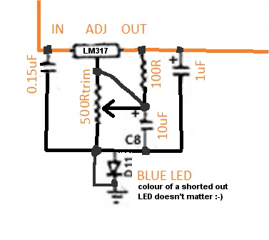
Here is the schematic as recently tested.  In this configuration I don't get above 6.5 VDC with R15 more than about 2-3 Ohm. No matter to what I set the LM317 trim pot to.

(R15 to 5R6 = about 5V at LM317 output). For some reason connecting the diode between the regulator circuit and ground brings the voltage up a bit.
 

Attachments

  • Alctron PSU_LM317.jpg
    Alctron PSU_LM317.jpg
    172.8 KB
I'd rather increase capacitor voltage and quality than just capacitance for the C8 and C9. I have five PSUs of this type. When the same problem with these caps happened the second time I just decided to recap them all, even the new ones, with good Pana caps (I am blessed to have a local distributor nearby my studio). You may consider moving the transformer closer to the side of the chassis, it'll help to put larger cans in if they don't fit.
 
Thanks so much for your input dbelousov!

Last friday I have put both power supplies back together. One has the LM317 circuit, the other one had the original 7806. In both PS I have replaced the 30 Ohm resistor with a 2 Ohm resistor - might not be optimal, but in both cases they give out the correct heater voltage now, the LM317 circuit being more precise obviously, with 6.29VDC measured at pin4/5 of the tube - which should be perfect, right?

Anyway, so I tried my luck and connected the microphones and the good news is, I DO get a signal. However I have more problems now: The mic has a VERY low output, I need to crank the gain up to max almost, which would make it about 45-50dB of gain boost. That is way more than the brand new and working Alctron BV300 I tested a couple of weeks ago, and besides, I get this nasty hum (sounds and looks a lot like a 50Hz+harmonics when I turn the analyzer function in the DAW eq on).

Poooooh, any hint where to start looking for this problem? btw so far I can't rule the cable out... I'll try tomorrow if a different cable works well (so far the issue was apparent with both mics and both PS, but I never tried it with another 7-pin cable)...

Also, the high voltage DC line (B+ or what is it called?) is at around 155 VDC, and when I measure the voltage at pin 1 of the tube it gives 100-105 VDC, does that sound correct?

Thanks so much, I really really really appreciate all your time and help. I'm really learning a lot in this process!!!
 
Just plug your cable in and check what you get on the other end.


1. 155
2. 6.3
3. 60 (fig-8), 25 (cardioid)
4. G
5. XLR3 2 or 3
6. XLR3 3 or 2
7. G

5 and 6 must not be shorted to each other or to the ground.
 
xeawr said:
Here is the schematic as recently tested.  In this configuration I don't get above 6.5 VDC with R15 more than about 2-3 Ohm. No matter to what I set the LM317 trim pot to.

(R15 to 5R6 = about 5V at LM317 output). For some reason connecting the diode between the regulator circuit and ground brings the voltage up a bit.
No wonder why it is operating a little strange.
Your 320R set the current of the Vreg to 1.25V/330R=3.9mA max., further decreasing with dialing the trimmer. If your vreg should operate predictable, set it to at least 12mA in order to make it fit even for a Fairchild 317 type. TI or NationalSemi FI are lesser demanding with 10mA. (The 5mA min.current is for the LM117 part, not the LM317 part). Short out the trimmer wiper with the vreg.adjust pin. Voltage setting network is Vout=Vref(1+Rvar/Riset)=1.25V(1+Rvar/100R). For 6.3V out, your trimmer Rvar (now wired as rheostat, not as voltage divider) will be set to about 404R. Replacing your 5K trimmer with a 500R part will make this adjustment for the desired output voltage a little easier.
xeawr_1.png
 
Thanks Harpo! Your help is appreciated! If time permits I will rewire the LM317 board tomorrow. In the meantime I have acquired two NEW Alctron BV300 power supplies. I'm so curious to see if the mics work with those, and I'm also curious how they measure (curious about the value of R15, voltage drop under load etc.)

I still haven't had enough time to even try with a different cable, to see why both microphones have this (relatively) loud hum. Also, the low output is still mystery. I thought the output is largely determined by the tube type, and ironically the last mic (same model, same tube type) had a noticeably louder signal (the output is low with both power supplies - even with the one with the working 7806). I will also post all voltage measurements of the mic tomorrow...

hope I'm able to bring the output up to a workable level (50dB of preamp gain is a bit much) and get a clear signal :) . I'm still thankful for any kind of hint or direction - where to look for those two problems (regarding the mics)...
 
I've found that there are two versions of this mic, with 60V and 30V capsules so my claim about 0-60V for the pattern switch may be wrong. I have had an experience with the 30V type only and checked its capsule with 60V, the backplate just sucked the membrane, making the capsule unusable, but it was fine with 25-30V.
 
Hi guys, it took me forever to get back to you. Last thursday I moved to germany with my girlfried and packing our stuff left no time to fiddle with the mics. I just had barely enough time to reassemble everything and do a couple of quick tests. Now I am 300km away from those mics, so the measurements will have to wait a bit, also I will undo the LM317 circuit (thank you Harpo for your help), and pop in a 7805 with suitable diode as previously recommended (by Khron if I remember correctly). So far the news are:

Both mics work with the new ("t.bone Retro Tube II" - a branded alctron BV300A) power supplies. They give out 6.7V heater voltage (as expected) but I didn't dare to open them to measure other components.

In comparing the original Alctron power supplies with the new ones I noticed that both old (repaired) ones have significant amount of hum (prettyl loud at around 150 and 250 Hz) vs the new ones under the same conditions. It can't be the LM317 circuit, because the second original PSU still has the original 7806 - just replaced the R15 resistor with 2R2 and the faulty 1000uF cap. Any idea where that could be coming from or how to track it down?

As for the mics themselves, I still have couple of questions regarding some modifications, should I open a new thread for that?

btw I'm with RuudNL, it propably would have been quicker to take a bit of perfboard and build a new circuit... but then again, I've so been haunted by the hum and voltage problems, it was an utter defeat until now, that I don't feel like touching any PS ever again  ::).
 

Latest posts

Back
Top