DI/Reamp Theory Questions

GroupDIY Audio Forum

Help Support GroupDIY Audio Forum:

This site may earn a commission from merchant affiliate links, including eBay, Amazon, and others.
squarewave said:
I'm not familiar with the "gain non-linearities" you speak of but most tube amp inputs are going to have a significant grid stopper (Fender 5F6-A is 68k||68k). So if series resistance with the grid is already 34k, is adding another 30k for the guitar going to matter to these non-linearities?
Resuming the guitar impedance to a simple resistor is not realistic; there is a large inductive component. The actual impedance may vary in a 1:20 ratio.

The only effect of the guitar source impedance that I'm aware of is it's interaction with the capacitance of the cable.
To which you must add the Miller capacitance of the input stage. The Miller capacitance being the product of Cag by  gain, all non-linearities of gain translate in non-linearities of the capacitive component of the input impedance. Since it introduces current NFB, the actual distortion may be slightly lower than with a low source impedance; however, when the source impedance becomes largely inductive, the phenomenon reverses and NFB becomes actually PFB, with an increase in distortion.
 
abbey road d enfer said:
No, we haven't recommended that. The high-Z side should be receiving the line level, and the low-Z side go to the amp, which takes care of the attenuation needed to avoid overdriving the amp's input stage. In doing that, the amp is presented with a very low impedance, which is not right for the purpose of recreating the guitar-amp interaction. In order to do that, an additional LRC circuit should be added. However, the main part of using an amp is the loudspeaker/air/room interaction, that is not lost; many SE's are satisfied with that and do not go the extra mile of simulating the impedance of the guitar.
That's why we don't recommend it.
It can be done easily by inserting a resistor of a few dozens kiloohms in the output. Alternatively, you can install a 500k potentiometer there, which will also allow level trimming.
Actually, there are many possibilities in this respect, like adding the aforementioned LRC circuit.

Ah ok, fantastic, I understand now. Thank you, sir. I’ll look into LRC networks and possibly just insert a resistor in that path to hear how it affects the sound. I do understand you however in that the desired effect of bringing the recorded sound into a space is achieved either way.

I am copying myself I know, but could you explain this following behavior?

When the above reamp is inserted in line level - DAC > 200/50k > ADC, it does not affect the gain at all, sounds 1:1/unity practically, maybe .2 dB difference. Sounds great and rich. Is this potentially damaging either side of the connection based on the loads squarewave was describing?

Thanks,
MG
 
MrG said:
-Reamping is where this gets confusing to me, and I’m still trying to make sure I’m clear. In my attempt to run line level out of my DAC to my transfo DI backwards (200 > 50k) it sounds like I’m doing something you all think is wise, in that I’m raising the impedance of the source drastically, and making it resemble a pickup, effectively. However, the signal is unusably loud... How would one ever raise the impedance that much without boosting the line level signal through the roof?

Best,
MG

Remember, a guitar signal is quite high and with some pickups can reach line level. When you DI, the transformer drops the level and then the mixer brings it back up to line level for recording to tape.

When you reamp through the DI transformer backwards, you start off at line level, which is already plenty to drive the guitar amp, and then boost it further through the transformer, so it is no wonder the signal is too hot. You probably want to retain this actual transformer because its secondary acts similarly to a guitar pick up; you just need to lower the level going into it.

So I suggest you connect a 1K audio taper pot between hot and cold of your DAC output and connect the transformer 600 ohm winding between the pot slider and the cold. This will allow you to adjust the level going into the transformer so that its output is more nearly the same as an actual guitar would produce.

Cheers

Ian
 
MrG said:
When the above reamp is inserted in line level - DAC > 50k/200 > ADC, it does not affect the gain at all, sounds 1:1/unity practically, maybe .2 dB difference. Sounds great and rich. Is this potentially damaging either side of the connection based on the loads squarewave was describing?

Thanks,
MG

Are you sure? Think you wrote the opposite earlier.

50k:200 is 250:1 impedance ratio

50k:200 is 15.8:1 voltage ratio or turns ratio.

DAC > 50k:200 > ADC should drop the signal by 15.8x, about 25 dB

DAC > 200:50k >ADC should raise the signal by 15.8x, about 25 dB
BUT impedances will be severely compromised for this case. DAC output is probably about 50 ohms.  ADC input is probably about 10k. So DAC will see ADC divided by impedance ratio,  10k / 250 = 40. Since the load is now really low and comparable to the DAC output impedance you will not get the voltage gain expected.  Best case is you get extra distortion.  Worst case you exceed the limits of the DAC and output burns up if it doesn't have adequate built in protection.

So in general that's not recommended.  But double check the ADC / DAC specs to confirm things.
 
MrG said:
I am copying myself I know, but could you explain this following behavior?

When the above reamp is inserted in line level - DAC > 50k/200 > ADC, it does not affect the gain at all, sounds 1:1/unity practically, maybe .2 dB difference. Sounds great and rich. Is this potentially damaging either side of the connection based on the loads squarewave was describing?
I already answered that question. The xfmr wants to elevate the signal, but the low-ish impedance of the line input squashes the signal of the 50 kiloohm output.
 
ruffrecords said:
Remember, a guitar signal is quite high and with some pickups can reach line level. When you DI, the transformer drops the level and then the mixer brings it back up to line level for recording to tape.

When you reamp through the DI transformer backwards, you start off at line level, which is already plenty to drive the guitar amp, and then boost it further through the transformer, so it is no wonder the signal is too hot. You probably want to retain this actual transformer because its secondary acts similarly to a guitar pick up; you just need to lower the level going into it.

So I suggest you connect a 1K audio taper pot between hot and cold of your DAC output and connect the transformer 600 ohm winding between the pot slider and the cold. This will allow you to adjust the level going into the transformer so that its output is more nearly the same as an actual guitar would produce.

Cheers

Ian

Thanks for this, Ian. I’m interested as to if there are any theoretical sonic “improvements” to be had between doing it this way on the input, and doing as Abbey Road has suggested and putting a resistor or LRC network on the output.

john12ax7 said:
Are you sure? Think you wrote the opposite earlier.

50k:200 is 250:1 impedance ratio

50k:200 is 15.8:1 voltage ratio or turns ratio.

DAC > 50k:200 > ADC should drop the signal by 15.8x, about 25 dB

DAC > 200:50k >ADC should raise the signal by 15.8x, about 25 dB
BUT impedances will be severely compromised for this case. DAC output is probably about 50 ohms.  ADC input is probably about 10k. So DAC will see ADC divided by impedance ratio,  10k / 250 = 40. Since the load is now really low and comparable to the DAC output impedance you will not get the voltage gain expected.  Best case is you get extra distortion.  Worst case you exceed the limits of the DAC and output burns up if it doesn't have adequate built in protection.

So in general that's not recommended.  But double check the ADC / DAC specs to confirm things.

Thank you for pointing this out and you’re exactly right, my apologies. I have corrected the several occurences of my mistake in previous posts.

Regarding your explanation, this makes great sense and clears up my understanding even further. Question: if DAC is ~50 ohms and it’s seeing the ADC as ~40 ohms, isn’t that a “match”? Correspondingly, am I correct in thinking the ADC @ 10k would see the DAC at (50 * 250) 12.5k, which is also approximately “matching”? In what situations does one concern themselves with damaging devices via impedance issues like this?

abbey road d enfer said:
I already answered that question. The xfmr wants to elevate the signal, but the low-ish impedance of the line input squashes the signal of the 50 kiloohm output.

Yes, again my apologies, I did see you said this. I was trying to ask more specifically  how there was virtually no gain change at all, but I know my understanding is limited here. I’ll get up to speed soon.

Thanks all,
MG
 
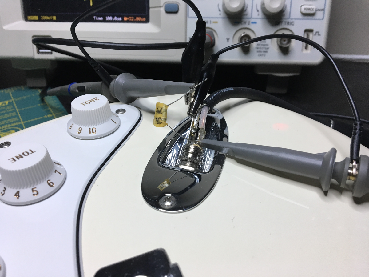
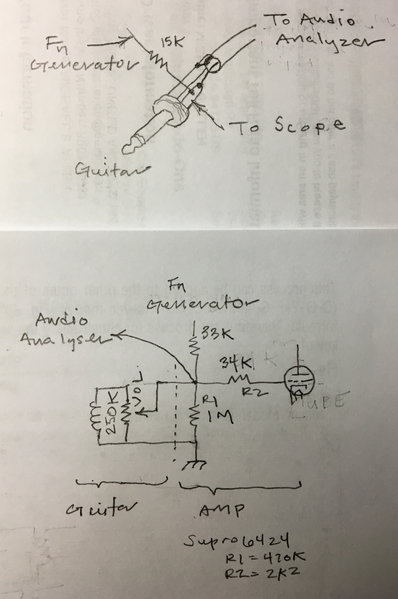
I found an interesting way to look at the output impedance spectrum of the guitar (maybe this is a standard test?). I used a circuit like the following:

GuitarImpedance1.png


GuitarImpedance0.png


So this is function generator -> 500Hz 400mVpp sine -> 15k resistor (33k in the lower drawing should be 15k) -> signal conductor of guitar plug -> guitar. With a 15k resistor, level at the signal conductor becomes 200mVpp which is 6dB attenuation and thus guitar impedance is ~15k at 500Hz.

Then I switch the stimulus to the audio analyzer and get the input from the end of the guitar cable. Then I can view the frequency response in real time as I play with the controls. I can "see" how each control affects the frequency response / level.

I didn't realize that turning the volume control back even a little totally negates the tone controls. The response just goes flat as a pancake.

So I didn't plug it into an amp but I suspect the results would be about the same. So the impedance of a vanilla MIM fender strat is ~15k. I bet a nicer guitar would be a little higher though.
 
MrG said:
Question: if DAC is ~50 ohms and it’s seeing the ADC as ~40 ohms, isn’t that a “match”?
Outputs have a load for which they are designed to deliver the specified performance. That load is usually 600 ohms for pro gear. The output can handle more load (it can provide more current). You could probably go down to 50 ohms or so. But it would be a little distorted. So yes it's a match, but not a good way.
 
ruffrecords said:
Remember, a guitar signal is quite high and with some pickups can reach line level. When you DI, the transformer drops the level and then the mixer brings it back up to line level for recording to tape.

When you reamp through the DI transformer backwards, you start off at line level, which is already plenty to drive the guitar amp, and then boost it further through the transformer, so it is no wonder the signal is too hot. You probably want to retain this actual transformer because its secondary acts similarly to a guitar pick up; you just need to lower the level going into it.

So I suggest you connect a 1K audio taper pot between hot and cold of your DAC output and connect the transformer 600 ohm winding between the pot slider and the cold. This will allow you to adjust the level going into the transformer so that its output is more nearly the same as an actual guitar would produce.

Cheers

Ian

Ian, I’ve been thinking on your solution and have a thought:

-I’d like to simplify this particular design and not use a pot, but rather a resistor to drop the signal approximately 30-40dB. One thing regarding your comment above,?the lower impedance side of the xfmr is 200, not 600. What value of resistor/resistors would I need to drop it 30 or 40db, and how is that calculated? I saw some comments on a Bo Hansen DI thread but I didn’t understand particularly why it seemed the resistors in paralell on the pad were different, and how they came up with a decibel value.

squarewave said:
Outputs have a load for which they are designed to deliver the specified performance. That load is usually 600 ohms for pro gear. The output can handle more load (it can provide more current). You could probably go down to 50 ohms or so. But it would be a little distorted. So yes it's a match, but not a good way.

What resistors/caps would I need to add to the DAC side of the xfmr to bring the impedance up to a more reasonable line level impedance, like say 600 ohms. (I believe my apollo interface outputs are 100 ohm, by the way.)

Thanks very much,
Mark
 
MrG said:
Regarding your explanation, this makes great sense and clears up my understanding even further. Question: if DAC is ~50 ohms and it’s seeing the ADC as ~40 ohms, isn’t that a “match”? Correspondingly, am I correct in thinking the ADC @ 10k would see the DAC at (50 * 250) 12.5k, which is also approximately “matching”?
That is only partially correct, because transformers are not perfect. Windings have a DC resistance that is considered almost negligible when used within the design limits, but take a much greater importance when using out of limits.
Even if the xfmr was perfect, you would have 12dB attenuation from matching, 6dB at the input and 6 dB at the output. Matching involves 6dB loss.
But in addition you have resistive loss, that would account for the additional loss you encounter.
 
squarewave said:
I found an interesting way to look at the output impedance spectrum of the guitar (maybe this is a standard test?).

With a 15k resistor, level at the signal conductor becomes 200mVpp which is 6dB attenuation and thus guitar impedance is ~15k at 500Hz.

Then I switch the stimulus to the audio analyzer and get the input from the end of the guitar cable. Then I can view the frequency response in real time as I play with the controls. I can "see" how each control affects the frequency response / level.

I didn't realize that turning the volume control back even a little totally negates the tone controls. The response just goes flat as a pancake.

So I didn't plug it into an amp but I suspect the results would be about the same. So the impedance of a vanilla MIM fender strat is ~15k. I bet a nicer guitar would be a little higher though.
I would agree with only one point: the impedance at 500Hz being about 15kohms. With the level pot at 6dB attenuation (that's pretty close to the top, not half-rotation) the impedance at 500Hz would be about 65kohms, but you should see a resonance at about 5kHz, with a maximum at about 100kohms.
Indeed, below that -6dB attenuation, the impedance tends to be governed mainly by the part of the potentiometer between output and ground. At half-rotation, which is about 20dB attenuation, the impedance is almost purely resistive at about 22kohms.
But many guitarists play with the volume pot fully cranked (particularly in solos), and that's where there are the most significant impedance variations, from 6k at 100Hz to 12k at 500Hz to 120k at 5kHz.
Definitely, you can't reduce the impedance of a Strat to a single value of 15kohms.
BTW, your methodology is not adequate, since the 15k resistor creates an error of 50% for a nominal impedance of 15kohms and 80% for 100kohms. That's because, AC-wide, the 15k resistor is in parallels with the DUT.  Your method also does not take into account that reactive impedances do not combine algebraically with resistors.
 
abbey road d enfer said:
That is only partially correct, because transformers are not perfect. Windings have a DC resistance that is considered almost negligible when used within the design limits, but take a much greater importance when using out of limits.
Even if the xfmr was perfect, you would have 12dB attenuation from matching, 6dB at the input and 6 dB at the output. Matching involves 6dB loss.
But in addition you have resistive loss, that would account for the additional loss you encounter.

Thank you again, Abbey Road. Very informative. So when you say matching, you mean the fact that the impedances are similar, as opposed to the signal flow seeing a higher impedance, e.g. the DAC out of ~100 ohms (found the specs), going into a higher impedance like 600?

What is a safe way to drive the input of a transformer? Is it ever safe/acceptable to go from higher impedance to a lower impedance to get the distortion characteristics? Or would you go lower fo higher impedance on the input and then use something like an opamp to boost gain.

I researched last night and I think I understand now that one “ideal” is for the above to happen: output impedance flows into a higher input impedance, often 10 times higher. So in this case, there would not be attenuation, correct?

Do you have any thoughts on adding resistors to pad the input of the reamp (200) between 30 and 40 dB so I can use the high impedance side to simulate a pickup’s interface with the amp?

I hope this thread is helping others, but I will say it is helping me greatly. Much appreciated.

Thanks,
MG


MrG said:
Thank you again, Abbey Road. Very informative. So when you say matching, you mean the fact that the impedances are similar, as opposed to the signal flow seeing a higher impedance, e.g. the DAC out of ~100 ohms (found the specs), going into a higher impedance like 600?
Correct; matching implies source impedance and receiver impedance to be equal, resulting in 6dB voltage loss. Seems rather wasteful, isn't it? But there are some good reasons to do it, in radio, long-distance lines, ..., but not often in audio applications.

What is a safe way to drive the input of a transformer?
A xfmr should be driven by the lowest possible impedance. Driving with a high impedance results in distortion - which you may like - but also results in poor frequency response.

  Is it ever safe/acceptable to go from higher impedance to a lower impedance to get the distortion characteristics?
Distortion is a matter of power; you can get distortion with a low level in a low impedance or a high level in high impedance.

Or would you go lower fo higher impedance on the input and then use something like an opamp to boost gain.
I'm not sure I understand fully your question. If you mean using the xfmr as a step-down, you may have to find a way to recoup some gain in order to compensate.

I researched last night and I think I understand now that one “ideal” is for the above to happen: output impedance flows into a higher input impedance, often 10 times higher.
That's pretty much the definition of "bridging", as opposed to matching.

So in this case, there would not be attenuation, correct?
That's correct.

Do you have any thoughts on adding resistors to pad the input of the reamp (200) between 30 and 40 dB so I can use the high impedance side to simulate a pickup’s interface with the amp?
You could use a potentiometer in series (anything between 1k and 22k) and see if you like it.
 
abbey road d enfer said:
Correct; matching implies source impedance and receiver impedance to be equal, resulting in 6dB voltage loss. Seems rather wasteful, isn't it? But there are some good reasons to do it, in radio, long-distance lines, ..., but not often in audio applications.
A xfmr should be driven by the lowest possible impedance. Driving with a high impedance results in distortion - which you may like - but also results in poor frequency response.
Distortion is a matter of power; you can get distortion with a low level in a low impedance or a high level in high impedance.
I'm not sure I understand fully your question. If you mean using the xfmr as a step-down, you may have to find a way to recoup some gain in order to compensate.
That's pretty much the definition of "bridging", as opposed to matching.
That's correct.
You could use a potentiometer in series (anything between 1k and 22k) and see if you like it.

Thank you, Abbey Road.

Re the potentiometer, my main goal in asking about a resistor/resistors instead of a pot is to avoid adding it to the layout and simplifying the interface. What resistor(s) would you recommend instead to achieve like 30-40db attenuation?

Regarding the distortion concept, you mentioned it’s a matter of power. The thing I’m looking for is a way to achieve distortion from the xfmr in a safe way - I don’t want to fry or damage any outs/ins. I understand once again that this may be basic, but what is a good practice and practical example of setting up a circuit to purposely distort an xfmr?

As an example, I’ve got Beyerdynamic peanuts at both ~200 and 50k, both 1:1, and I’m trying to figure out a healthy way to distort them.

Thanks,
MG
 
MrG said:
Re the potentiometer, my main goal in asking about a resistor/resistors instead of a pot is to avoid adding it to the layout and simplifying the interface.
My suggestion was to put a potentiometer, find a point where you like it,measure the pot and  and replace it with a resistor of same value.

What resistor(s) would you recommend instead to achieve like 30-40db attenuation?
Can't tell; so many variables I can't figure that by calculation. Trial and error is the only way.

I understand once again that this may be basic, but what is a good practice and practical example of setting up a circuit to purposely distort an xfmr?
Same answer, too many variables.
 
abbey road d enfer said:
My suggestion was to put a potentiometer, find a point where you like it,measure the pot and  and replace it with a resistor of same value.
Can't tell; so many variables I can't figure that by calculation. Trial and error is the only way.
Same answer, too many variables.

Thank you for clarifying and I understand. I’ll experiment with a pot.

Just to be clear on my question about distortion, earlier, I believe John12ax7 mentioned potential distortion due to the output of the DAC being ~100 ohms and it seeing the input of the ADC as ~40 ohms. He said this could damage the output of the DAC. I’m trying to figure out in what types of scenarios damage can occur from this type of impedance mismatch (~100>~40), or if I can enjoy this distortion without damaging anything. If my question is still too vague to be answerable, I won’t ask it again, or I can do my best to provide more info.

Thank you very much,
MG
 
MrG said:
Thanks for this, Ian. I’m interested as to if there are any theoretical sonic “improvements” to be had between doing it this way on the input, and doing as Abbey Road has suggested and putting a resistor or LRC network on the output.
Thanks all,
MG

Depends on your definition of improvement. Electrically they are very similar but not identical. One may be more pleasant to your ear than the other. Only you can tell.

Cheers

Ian
 
MrG said:
Ian, I’ve been thinking on your solution and have a thought:

-I’d like to simplify this particular design and not use a pot, but rather a resistor to drop the signal approximately 30-40dB. One thing regarding your comment above,?the lower impedance side of the xfmr is 200, not 600. What value of resistor/resistors would I need to drop it 30 or 40db, and how is that calculated? I saw some comments on a Bo Hansen DI thread but I didn’t understand particularly why it seemed the resistors in parallel on the pad were different, and how they came up with a decibel value.

Thanks very much,
Mark

You need a 30dB or 40dB pad. 30dB is 330 0 times so the output leg of the pad needs to be one about one 30th of the input leg. The output leg also needs to be low enough to feed the transformer. Since its is not clear what this is lets go for 100 ohms. The input leg needs to be 30 times this or 3K. Lets make it balanced so split the 3K into a pair of 1K5 resistors. So wire 1K5 from DAC hot to 100 ohms. Other end of 100 ohms to other 1K5 and other end of this 1K5 to DAC cold. Feed the transformer from either end of the 100 ohms.

Cheers

Ian
 
There are two general ways to transfer signals. One is a matched system where load impedance equals source impedance.  Good for power transfer,  long distances,  high frequencies. RF is typically 50 ohms,  video is 75, old school audio was 600, an 1176 is 600 ohms.

The other way is called bridging,  the load impedance is much higher than the source so you have minimal voltage loss.  Modern line level audio uses this. So a typical modern circuit works very well driving a high impedance, for example 10k. But people still want to use their old school gear,  like an 1176. So something like a NE5534 is designed to still work acceptably at 600 ohm load.

The problem then becomes what if you go lower than 600. There is not a simple answer. It will depend on the drive capability of the output stage and if it can handle the excess drive needed. A very robust design will safely limit the current, where even a short circuit on the output will do no long term damage.  Other designs might be permanently damaged.  Best to ask the manufacturer what is the minimum load that can be safely driven.

If you have 1:1 transformers they can be used without worry about the DAC.  You can get saturation by driving the transformer harder, see if you like the sound.  Just double check if there is an absolute max rating on the transformer.
 
john12ax7 said:
There are two general ways to transfer signals. One is a matched system where load impedance equals source impedance.  Good for power transfer,  long distances,  high frequencies. RF is typically 50 ohms,  video is 75, old school audio was 600, an 1176 is 600 ohms.

The other way is called bridging,  the load impedance is much higher than the source so you have minimal voltage loss.  Modern line level audio uses this. So a typical modern circuit works very well driving a high impedance, for example 10k. But people still want to use their old school gear,  like an 1176. So something like a NE5534 is designed to still work acceptably at 600 ohm load.

The problem then becomes what if you go lower than 600. There is not a simple answer. It will depend on the drive capability of the output stage and if it can handle the excess drive needed. A very robust design will safely limit the current, where even a short circuit on the output will do no long term damage.  Other designs might be permanently damaged.  Best to ask the manufacturer what is the minimum load that can be safely driven.

If you have 1:1 transformers they can be used without worry about the DAC.  You can get saturation by driving the transformer harder, see if you like the sound.  Just double check if there is an absolute max rating on the transformer.

Thanks for this, John. So when you say an 1176 is 600, do you mean that the input and output impedance are both 600? Is most old school line-level equipment effectively 1:1 in this way? And nowadays it’s a high input bridging impedance of ~10-20k(?), and a lower output impedance of ~600 (or lower?)?

I hear you about 1:1 xfmrs and am already using this a bunch in application. I’m about to install a switch on my WE 111cs to drop the secondary from 600 to 140 and am also trying to think through all of this theory before using that in series with other line level equipment.

Best,
MG
 

Latest posts

Back
Top