digitally controlled stepped attenuators..??

GroupDIY Audio Forum

Help Support GroupDIY Audio Forum:

This site may earn a commission from merchant affiliate links, including eBay, Amazon, and others.
A fast detector that controls a fine-stepped resistive attenuator--talk about the ultimate "transparent" automatic gain control! Gentlemen, if you can perfect this idea, you'll have a very marketable product on your hands.
 
[quote author="PRR"]I know the PICs run machine language and a 2MHz machine ought to be fast enough. But I won't write machine code (been there). Can you write in a higher level language and get clean code?[/quote]
Yes. I write most stuff in C. But you have to know what you're doing - you have to write assembler-like C code sometimes. You also have to write code that uses the fast instructions rather than the slow etc.

I don't use PICs though - I use different '51 clones. Available with speeds up to 100 MIPS. I think a 1-2 MIPS version should be more than enough for this though.

If you could provide some suggestions (how fast should the level be adjusted, how much etc.) I'll have a look at it. Doesn't sound too difficult...

Best regards,

Mikkel C. Simonsen
 
Here are the sinewaves (with a bit of random noise thrown in).

http://62.242.11.12/Shalimar/Sine.wav (1kHz)
http://62.242.11.12/Shalimar/Sine2.wav (100Hz)

I can see the "click" on the 100Hz wave. Have a look here: http://stiftsbogtrykkeriet.dk/~mcs/Relay_glitch2.gif

Best regards,

Mikkel C. Simonsen
 
I'll listen to the sines at work; don't want to wake the dog.

> I can see the "click" on the 100Hz wave.

I was expecting something more like as shown on the right:

glitch.gif


A hole or spike in the audio. A steep part of the wave is "perfect", as perfect as a discrete-step system can be.

> I use different '51 clones.

Ah! Stripped-down souped-up 8080s! Most popular CPU on the planet. Lovely non-orthagonal instruction-set similar-to (but not same-as) the charming 8080.

> If you could provide some suggestions (how fast should the level be adjusted, how much etc.)

Gosh. It was some years back when I was thinking of it, and don't seem to have a scrap of pseudo-code laying around now. Anyway I had some clever ideas that were probably over-clever. But that is part of the charm of doing AGC control in the digital domain: some things that are hard in analog peak detectors and time-constants are easy in digital (and vice-versa) so the "ideal" PIC/CPU/Stamp would be easily modified in a jiffy, not a write-once ROM programable.

Basically:

We probably still need an analog peak-holder, a rectifier and a cap. And a comparator: if the voltage on the cap exceeds (say) 2.0V, then we are close to our 2.8V maximum allowed level and need to reduce gain.

Although if the CPU has proper hardware interrupts, we might get away with a real-time no-cap comparator: if the instantaneous signal level exceeds 2.0V, an interrupt is thrown.

Before the concert starts, the operator dials-in a gain, based on sound-check, experience, or counting the players on stage. If signal level never goes over 2.0V, then this is the gain that stays in effect for the whole take.

If the signal level "surprise!" exceeds 2.0V, the CPU should reduce gain. Say 1dB.

If the level still exceeds 2.0V, CPU should reduce gain again.

Conceptually we have two variables: User_set, and GR.

BUT: if the CPU can check the level every microsecond, and the relays take a millisecond to flip, then the CPU could turn gain down 1,000dB before the relays respond to the first command.

Also if using a peak-hold level detector, the detector should be discharged when relay-setting changes, so it does not retain the now-invalid level but has to acquire the new reduced-gain level. (In analog GR processing, the cap must retail the level because this is the Release function too. In digital we will compute the release action digitally.)

So: if level is Over, reduce gain, wait for relays and peak-hold to settle, check level, repeat as needed.

When gain is reduced enough (or peak passes), the CPU defaults to holding the last gain setting. i.e. if User_set was 40, and gain had to be reduced 3dB to avoid going Over (GR=3), then gain stays at 40-3= 37.

Normally we want gain to recover when the loud part passes. Just as an example: if not-Over, and GR is not zero, then decrement GR one per second until it is zero. (That gives a slow release: in many applications we want faster than 1dB/second, but never more than 1dB per step to avoid volume-jump, so this decrementing has to happen more than once a second.)

That gives a constant dB/Second release, different from basic analog limiters which have nearly the same release time from 2dB or 20dB of gain reduction. I think a dB/Sec rule makes sense psychoacoustically, but we might discover otherwise.

One problem: if for relay and peak-hold settling reasons, GR is only incremented say every 2mS, Attack will be slow on large over-voltages. And if gain is reduced 1dB every 2mS, that is equivalent to a 500Hz -20dB buzz under the transient.

It might be nice if the settling time between GR increments were semi-random, to spread that pure 500Hz over the 300-700Hz band, so it does not stand-out to the ear as a tone.

Also if large over-level is common, we might add a 4V threshold, and if this is triggered we reduce gain 3dB in one step. Then large peaks are quickly knocked-down.

The release time should perhaps vary with signal. If the level has been low, goes high for a few mS, then goes low for a while, we should probably recover quickly from this unusual event. But if level has been loud, peaks, then goes back to loud, maybe we should recover very slowly to avoid pumping effect. We might even hold a fixed level.

So I had in mind a 3 threshold detector: 2V as the goal-level, 4V as the drastic-action level, and a 0.3V (-15dB) detector to indicate if historical (last second or two) levels have been high or low.

The old CBS designs had another feature: if GR was in effect, but level dropped to "nothing" (-40dB), then hold that last GR setting for a while: it is either a musical pause or an operator screw-up, and the program may come back at the same level, and should probably be at the same GR as before. (But if the "nothing" continues for many seconds, maybe it is supposed to be soft but maybe not THAT soft, and GR should be released slowly.)

So there are many "clever things that could be done. Some, like holding through pauses, are very hard to do on leaky caps and very easy on a CPU ("do nothing").

Oh: and while checking for over-level (top priority) and recovering from passed peaks, we need to check the knob/buttons for user input (maybe the operator has realized the mistake and wants to take the rest of the take at lower gain), and update the display (so the operator knows the GR and User_set values).

Your existing board has just one numeric display. Obviously a deluxe product would have separate User_set and GR displays. But one might be enough: if GR is zero, display User_set; if GR is happening, display GR. In many cases the difference is clear: User_set is generally 30 to 63, and GR is usually 1 to 20; User_set is fixed and GR will change with the signal. Also one LED could indicate that GR is being displayed. Changing the User_set should display the new User_set for one second, then go back to GR if it is non-Zero.

Just getting gain to drop if threshold is exceeded, and recover smoothly afterward, would of course be enough to try, see how it sounds.
 
[quote author="PRR"]so the "ideal" PIC/CPU/Stamp would be easily modified in a jiffy, not a write-once ROM programable. [/quote]
I often use an old development board that runs programs from RAM to do the testing. Otherwise all the (modern) chips have re-programmable flash memories.

Although if the CPU has proper hardware interrupts, we might get away with a real-time no-cap comparator: if the instantaneous signal level exceeds 2.0V, an interrupt is thrown.
The chip I use for the small control board (AT89C4051) has a "high precision analog comparator" built in (according to the datasheet). It simply sets/clears an SFR bit, so it is very easy/fast to read. I would probably do that in a while loop though - much faster than interrupts. The interrups could be used for the encoder/buttons.

Also if large over-level is common, we might add a 4V threshold, and if this is triggered we reduce gain 3dB in one step. Then large peaks are quickly knocked-down.
Then an external comparator would be needed - but that's not a huge problem either...

Your existing board has just one numeric display. Obviously a deluxe product would have separate User_set and GR displays. But one might be enough: if GR is zero, display User_set; if GR is happening, display GR. In many cases the difference is clear: User_set is generally 30 to 63, and GR is usually 1 to 20; User_set is fixed and GR will change with the signal. Also one LED could indicate that GR is being displayed. Changing the User_set should display the new User_set for one second, then go back to GR if it is non-Zero.
The reason there is only one display (and two digits), is to keep the size of the board down. And as the displays are run by the I/O pins directly, you quickly run out of pins also. When the board size is not a problem, you can just add a 4-to-7 decoder chip and run 5 displays with the same number of pins. You could also use an 8*1 or 8*2 LCD display instead.

Just getting gain to drop if threshold is exceeded, and recover smoothly afterward, would of course be enough to try, see how it sounds.
OK, I'll try then :grin:

How would you detect the volume level? Just use a single diode rectifier and into the comparator input?

Best regards,

Mikkel C. Simonsen
 
> How would you detect the volume level? Just use a single diode rectifier and into the comparator input?

This is CMOS technology, right?

As a first-hack: run a 10K resistor from the audio, after the relay-box, into any digital input pin. Read that pin several times a milliSecond. If pin is HIGH, reduce gain.

This will sense if peak audio is over about 2V, the threshold of the logic pin. Yes, it will miss some peaks, and won't see negative peaks, but will catch enough peaks to mostly-work, enough to try the algorithms.

You probably need an amp with gain of 10 or 20 after the relay-box to get the peaks up to over 2V. Or if you have a decent analog comparator pin, bias the reference to about 0.2V and check if the audio is over that.
 
I just did some tests on the 6-relay attenuator board. I used my 200CD oscillator and the voltmeter in a 334A distortion analyzer. I made two tests, one at 1kHz and another at 20kHz. I use tiny relays on my test board, so I was afraid of stray capacitance problems. You can see the attenuator part of the board here: http://stiftsbogtrykkeriet.dk/~mcs/Attenuator.jpg

These are the results:
Code:
Calc. att.  Att. @ 1k  Att. @ 20k
  63dB       62.69dB    62.75dB
  55dB       54.89dB    55.42dB
  47dB       46.94dB    47.46dB
  39dB       38.79dB    39.29dB
  31dB       30.95dB    31.33dB
  23dB       22.89dB    23.38dB
  15dB       14.89dB    15.08dB
   7dB        6.94dB     7.12dB

Doesn't look too bad to me... So I guess using miniature relays instead of standard DIL relays is not a problem.

Best regards,

Mikkel C. Simonsen
 
I forgot one test of course - crosstalk! I use the relays for two channels (or a balanced signal), so the crosstalk is important too.

I made some different tests. I tested with the "other" channel's input open, with a 680R resistor on the input and without and with a load on the channel with the signal. I got the best results with a load on both outputs, and with something connected to both inputs. That should resemble "real life" conditions the best also...

These are the results:

With no load on the signal-channel and the input of the other channel open I get the maximum crosstalk at full volume. The output signal is -50.65dB at 1kHz and -27.96dB at 20kHz.

With 680R on the other channels input I get -87.91dB at 1kHz and -61.94dB outputs at 20kHz. But's that not the maximum crosstalk. With these conditions I get the max. crosstalk at the -7dB step. The output is 44.44dB below the 3V input signal on the other channel (at 20kHz).

With both inputs and outputs terminated I get the maximum crosstalk at the -5dB step. The output is 47.07dB below the 3V input at 20kHz.

Now I would love to know if that's good, bad or terrible. I hope some of the more knowledgeable people here are reading this...

[edit]One thing I forgot to add. The attenuator used for these tests is a 50k version. I guess a 10k version would have less crosstalk?[/edit]

Best regards,

Mikkel C. Simonsen
 
I would not expect any significant difference between big and small relays.

> With both inputs and outputs terminated I get the maximum crosstalk at the -5dB step. The output is 47.07dB below the 3V input at 20kHz.

For a balanced one-channel attenuator, this is negligible. (It is in fact comparable to your frequency response error, and for the same reason.)

For a stereo-pair: a lot of snobs would sneer at -47dB crosstalk. It isn't bad, but some folks like to see numbers above 60 or 80 dB. Myself, even 20dB is fine.

If for some reason you were attenuating two different signals, -47dB might be a problem.

A lower impedance level would solve both the frequency response and the capacitive crosstalk. (I was thinking around 1K ohms for a very low-noise mike preamp gain control; you might want to think about 10K for general line-level potting.)

How is the zipper-noise on these small relays? When I first listened to your sample I heard big pops on the top three steps, but when I tried on another speaker I didn't, and careful waveform study shows absolutely insignificant wave-wobble. The wave HAS to be bent when you change the gain, but this odd ladder network and these relays don't make it any worse.
 
Mikkel, that sounds very nice for me. I'm still witing for my pcb's and making some resistor selection... Hope i will finnish soon :green:
 
[quote author="PRR"]I would not expect any significant difference between big and small relays. [/quote]
There was a difference - a big difference in some areas.

The worst case crosstalk at 1kHz (at -7dB) dropped to -82.12dB.
The worst case crosstalk at 20kHz (at -6dB) dropped to -56.67dB from -47.07dB.

So the crosstalk got improved, but the frequency response is a bit smaller. The worst case (of the settings I measured) was -30dB, where the actual attenuation was -31.16dB at 20kHz. At 1kHz it was correct.

But the problem is that I now get audible clicks when I change settings... So I guess the small relays are needed to get good performance. I will try a 10k "big relay" attenuator, to see if the impedance has any influence on the results.

Best regards,

Mikkel C. Simonsen
 
> I now get audible clicks when I change settings...

That makes sense. Really big relays take 10mS to throw from pole to pole, some teeny relays do it in 0.2mS. A gap over 1mS will be audible, glitches under 1mS less audible.

Big relays give less crosstalk? I guess the greater spacing between fingers makes up for the larger area of each finger.

Of course for the ultimate, you would use twice as many relays and separate relay per channel. But I think it is really clever the way you get good log steps and reasonably constant impedances with just one SPDT per channel, so a DPDT serves two channels.
 
I have now (finally) tested a 10k version of the attenuator board.

Code:
Calc. att.  Att. @ 1k  Att. @ 20k
  63dB       61.86dB    61.94dB
  53dB       52.98dB    52.99dB
  43dB       43.04dB    43.04dB
  33dB       33.12dB    33.14dB
  23dB       22.99dB    23.04dB
  13dB       12.97dB    12.97dB
It looks like the frequency response is better. It's now only 0-0.08dB down at 20kHz. I don't know why the -63dB results are so far off though...

The crosstalk has also improved. At the 0dB setting the crosstalk is -98.27dB at both 1 and 20kHz. At 1kHz the maximum crosstalk is at the -16dB setting, where the crosstalk is -68.41dB. At 20kHz the max. is at the -8dB setting where the crosstalk is -66.16dB.

Doesn't look too bad, for a simple circuit like this :grin:

Best regards,

Mikkel C. Simonsen
 
It looks fine so far.
:thumb:

the 63dB is not so bad ... small signals, cables, contacts, connections and all that.
I don't have a dual pot that would track as well as the above.

I want one of the above. :cool:
 
I have just drawn a two-channel balanced version. The board size is about the same (approx. 8*8cm). I have used separate drivers chips, so the channels can be controlled independently if needed.

Here's a drawing: http://stiftsbogtrykkeriet.dk/~mcs/RelVol3_PCB.gif

Best regards,

Mikkel C. Simonsen
 
Hi! I wonder do i have to go with this pcb :?: BTW, i have some problems with sending you atmels back... i will explain it one day :roll: Did you tested new software?
 
[quote author="Moby"]Did you tested new software?[/quote]
Yes, haven't you received my e-mail?

Best regards,

Mikkel C. Simonsen
 
This project was "on ice" over the year :oops: To be honest I was discouraged because of my poor digital electronics knowledge and also I had problems to fabricate boards in native Mikkel version. :cry:
BTW, my studio work don't give me so much time to DIY :?

But, here's the new start :thumb:
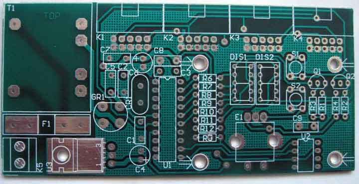
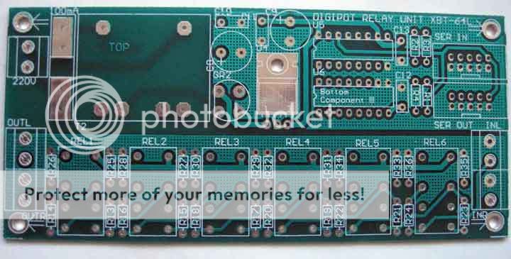
I rearranged the boards, included the few things like main TX and link connectors from board to board...
DIGIPOT-atmelboard.jpg

DIGIPOT-relayboard.jpg

Now I have to find the ATMEL chips :?
Of course, I put them on some "safe place", now I don't remember where :oops:
 
[quote author="Moby"]Now I have to find the ATMEL chips :?
Of course, I put them on some "safe place", now I don't remember where :oops:[/quote]
Are those the chips I sent you? If you can't find them, just let me know.

The boards look great!

Best regards,

Mikkel C. Simonsen
 
Back
Top