digitally controlled stepped attenuators..??

GroupDIY Audio Forum

Help Support GroupDIY Audio Forum:

This site may earn a commission from merchant affiliate links, including eBay, Amazon, and others.
[quote author="Moby"]
I rearranged the boards, included the few things like main TX and link connectors from board to board...
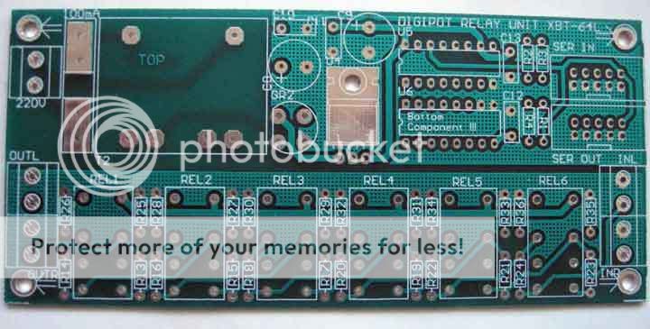
DIGIPOT-relayboard.jpg

[/quote]

Power transformer on the audio board? Aren't they too close to the circuits passing audio? :shock:

chrissugar
 
[quote author="chrissugar"][quote author="Moby"]
I rearranged the boards, included the few things like main TX and link connectors from board to board...
DIGIPOT-relayboard.jpg

[/quote]

Power transformer on the audio board? Aren't they too close to the circuits passing audio? :shock:

chrissugar[/quote]
Many commercial audio units have main TX integrated into board. Yes, that can be a problem, but I can always remove it if I found some trouble :green:
 
[quote author="mcs"][quote author="Moby"]Now I have to find the ATMEL chips :?
Of course, I put them on some "safe place", now I don't remember where :oops:[/quote]
Are those the chips I sent you? If you can't find them, just let me know.

The boards look great!

Best regards,

Mikkel C. Simonsen[/quote]
Yes Mikkel, I'm the complete idiot! I searched everywhere around, at home, at my studio. And I searched in the basement too!!!


BTW, can this control unit work without Eeprom? I'm asking because I ordered them from Buerklin and will wait week or more for them. If I find the Atmels can I make it work without 95040 just for testing?
 
[quote author="Moby"]
BTW, can this control unit work without Eeprom? I'm asking because I ordered them from Buerklin and will wait week or more for them. If I find the Atmels can I make it work without 95040 just for testing?[/quote]
No, probably not. The software will wait for the EEPROM to respond before doing anything. But just send me your address, and I will send you a couple of them.

Best regards,

Mikkel C. Simonsen
 
Few months before my control board finally started to work :thumb: There was stupid problem with pin reversed encoder. I was thinking that it's same from both side , but obviously it's not! Thanks to Mikkel for unselfish help :guinness: :sam:
I was really lost in my studio for the long time and it's really a time to finish this great project. I have all the boards stuffed and just need to solder the resistors on the relay board. But as always I'm asking Mikkel for help! I can't find values for 10k and 22k log versions :oops: Mikkel can you tell me that based on the schematics I used . I changed the resistors numbers so please tell me by "my" numbers :green:
 
I have e-mailed you the resistor values for 10k and 20k now. You will have to change the resistor numbers yourself :twisted:

But they are listed in the same order as on the schematic (I think) :grin:

Best regards,

Mikkel C. Simonsen
 
Thanks Mikkel. Just to be sure... numbers are from this schemo?
6bitatt2schovafc9.gif

Shot at 2007-07-20 BTW, for which attenuator are resistors values from picture?
 
Hi guys,

Would anyone care to comment on THIS remote Neve 1073x8?

Particularly the stuff that relates to this thread is:

Just as with the original 1073, there are 13 gain steps utilized throughout the 20-80dB range, however unlike the original 1073, all of the controls are MIDI accessible.

AND

the IC's are used for remote control and precision gain control through a stepped resistor network, but all audio paths are fully discrete.

What I'm wondering about is howcome those guys used ICs (which saves space and eliminates relay switching noise) instead of relays? What would be a disadvantage of IC-switched resistor network?

Thanks!
 
[quote author="mcs"]No, it has 256 steps from 0R to the max. value you decide. I think Bauman is trying to make a rev. log pot also.

Best regards,

Mikkel C. Simonsen[/quote]
That's the big problem with stepped pots; you can't expect them to offer constant dB-per-step. Whatever you do, you'll end up with only n steps of relevant value for an n bit system.
Constant dB-per-step can be achieved only through cascaded gain cells of increasing value.
 
[quote author="promixe"]What I'm wondering about is howcome those guys used ICs (which saves space and eliminates relay switching noise) instead of relays?[/quote]
ICs are cheap and reliable.

What would be a disadvantage of IC-switched resistor network?
They usually add a bit of distortion. The series resistance of fet switches can also be quite high, so if you're switching low-resistance gain resistors, you may need to trim the resistors to compensate for the varying internal resistance of the switches.

Best regards,

Mikkel C. Simonsen
 
Hi,

I just posted a topic on a similar subject as this but with a different intent in mind. I'm attempting to construct a relay substitute for logarithmic potentiometers, not an attenuator. Thus far I have succeeded in a circuit that puts out something that looks like an logarithmic curve with a "small" amount of components and sufficient number if steps (32 using 5 relays). However I'm having some trouble with "bumps" in the circuit (see graph). As many of you already know this type of circuit could be very useful in applications such as recall and automation and also to replace difficult to obtain potentiometers. I hope someone can help me sort this problem out so we can automate our DIY!

Link to the other thread.
http://www.groupdiy.com/index.php?topic=34103 

Best Regards,
Hampus
 
mcs said:
[quote author="pilo"]By the way it seems impossible to make a real log curve with it. I mean, each step decrease gain by 1db (or 2db, or any linear dB variations) and keeping the same value between in and gnd.
If you need a circuit with in, out and gnd connections (like a standard volume pot), you can use this circuit: http://stiftsbogtrykkeriet.dk/~mcs/6bitatt.gif

It has a fixed input impedance and a fixed stepsize (1dB with the values shown I think). The only requirement is that the load impedance is fixed - or large compared to the attenuator impedance. The attenuator could be expanded to 8 relays if you really need 256 steps, instead of the 64 you get with 6 relays.

Best regards,

Mikkel C. Simonsen
[/quote]

My brian can't figure how you get 64 steps with 6 attenuator values.  If they are 1dB steps from -1 to -6. My brain came up with only -21 as being the most attenuation
possible by daisy chaining all attenuation steps.  My brain hurts from this one. Can anyone ease the pain here.
 
My brian can't figure how you get 64 steps with 6 attenuator values.  If they are 1dB steps from -1 to -6. My brain came up with only -21 as being the most attenuation
possible by daisy chaining all attenuation steps.  My brain hurts from this one. Can anyone ease the pain here.

Here is the Optalgin:

Cascaded (daisy chained) attenuators 32-16-8-4-2-1.
Same input impedance, same load.

Gain control: use DigContrAtt as feedback divider.

Clicks solution: exists.

Attenuator PCB shown by Moby can be used in active CRM (coming soon).
IMHO power trafo should be removed from this PCB.
 
Thanks Igor.

I missed that each position is 2x atten.  I fail to see how the values in between are achieved though.
It's similar to your CRm right?

this article claims that cascaded attens are additive:
http://www.allaboutcircuits.com/vol_3/chpt_1/7.html

brains still hurts  ;)
 
guavatone said:
My brian can't figure how you get 64 steps with 6 attenuator values.  If they are 1dB steps from -1 to -6. My brain came up with only -21 as being the most attenuation possible by daisy chaining all attenuation steps.  My brain hurts from this one. Can anyone ease the pain here.
Stepwidth is different for each cascaded step, controlled by 6 bits = 2^6 or 64 steps. LSB controls the leftmost attenuator -0.12dB, followed by -0.45dB, -1.69dB, -5.6dB, -14.86dB up to MSB the rightmost attenuator -31.7dB.
All bits set/relays engaged giving -54.4dB attenuation on paper. Impedances in this passive voltage divider are different for each step or cascaded permutation (IE only bit 1 set, source sees 48k7+1k3=50k, load sees 1k3. Only bit 6 set, source sees 5k49+392k=~397k, load sees 392k. Bit 3+6 set, source sees 30k1+(33k2||(5k49+392k))=~79k3, load sees 33k2+(30k1||(5k49+392k))=~61k2).
 
Wow.  I'll have to hit the books.  The digital stuff is a stretch for me.

I can't see where the analog signal is manipulated by the programable chip other than the relay being switched on or off.
So are you saying that each relay position has many values in between the next relay?
 
guavatone said:
I can't see where the analog signal is manipulated by the programable chip other than the relay being switched on or off.
So are you saying that each relay position has many values in between the next relay?
No. The chips only control the relais. Each of the 6 relais controls a specific amount of attenuation. Just picking one side of K3 for examples sake, relais engaged, the 18k2 series resistor R7 and 84k5 shunt arm resistor R19 to gnd is in circuit, forming a voltage divider 84k5/(18k2+84k5)=0.823. This is log10(0.823)*20=-1.69dB. Relais disengaged, R7 is shorted out and R19 is disconnected, giving no attenuation in this section. Relais K4 activates a -5.6dB attenuator. If both K3 and K4 are engaged, attenuation is -1.69dB from an already by -5.6dB attenuated signal = -7.3dB, /edit: if each stage would be buffered individually. As this design is a passive attenuator (no active gain cells), each attenuator is loaded by the following stage, IE the -5.6dB from K4 would be -6.85dB, because the 33k2 shunt arm resistor R17 is in parallel to R7+R19, giving -8.54dB without external load connected. With external load connected, there would be even more attenuation.
 
Back
Top