Hi Joechris,
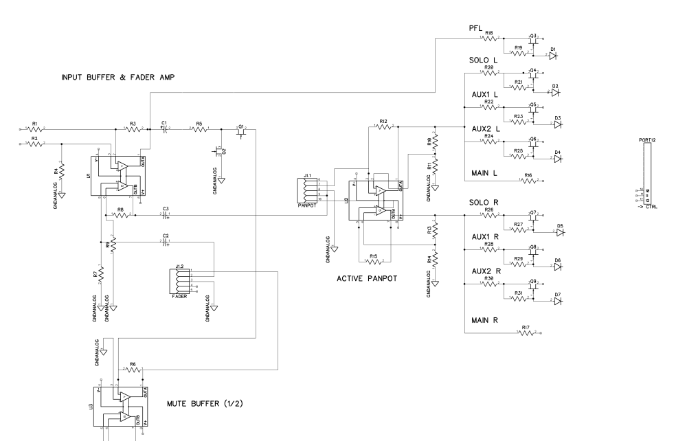
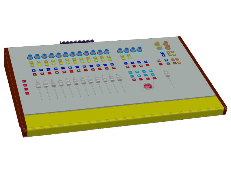
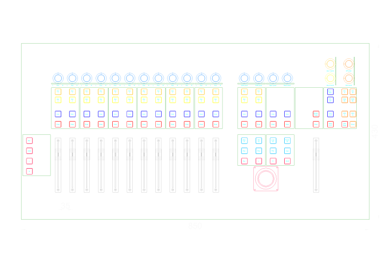
3d is done in standard Autocad - it's quite powerful and does 3d 'on request'.... I use the extrude command quite a lot to build 3D volumes. 'on request' because most of the time people don't know it has extensive 3D features. volumes can be subtracted or summed to build more complex forms, but here I had to use this only with the complicated bottom sheet that has non right angle bends to meet the top panel. I wanted to make this precise enough to get a decent result. with Autocad you can put objects on layers - and give them a dedicated color (per layer or block or object) the color scheme is not meant to be final at all, besides the switches that I kind of like.... I will try to put a 'parallel' version of the desk online, but it's really much more helpful in 3D when you can rotate and deselect layers to show the inner working of the design. I had to reassign the connectors a few times to make it all fit on the back side, it's quite crammed with the large power supply heat sink.
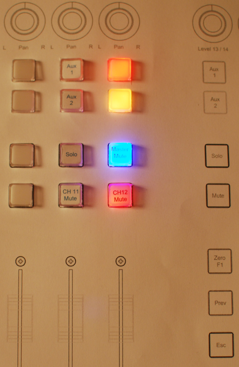
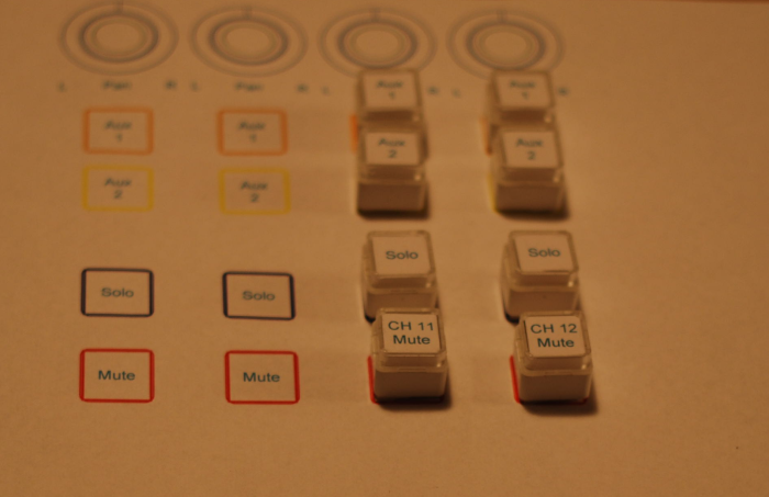
here's a update on color scheme with the right colour of the knobs... the only thing I know how it schould look like in the end...
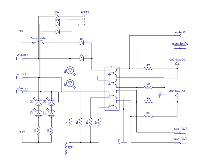
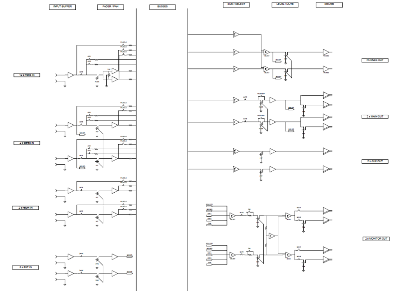
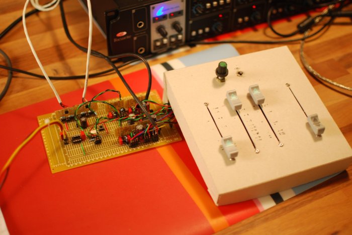
the switching is done with fets, as mentioned earlier. I use two modes - mute and switching. both designes originate from the studer / ssl and douglas self designs floating around. douglas selfs book on small circuit design has been particularly helpfull and I can only recommend it.
the mute switch uses a parallel and a serial fet, driven with opposite controls - the parallel fet will be high impedance when the signal is passed through and close to 50 ohm when the signal is muted. the serial fet is driven the inverted way. in my drive circuit I use two optocouplers to generate the opposite control voltages (-15V / 0V). both optocouplers are driven at the same time with their leds in sereis. one channel has 0V potential, the othe -15V. when off these are reversed. because the fets are voltage controlled the hole drive circuit can be high impedance. I have choosen this approach because it is a nice way to provide the -15V / 0V required with regular logic / microcontrollers and provides a completely decoupled control l/ audio circuit. the microcontroller just has to drive some leds....
the switching is a little easier, I can do it with one fet per channel, but I had to get the control voltage lower to maintain the control voltage below the music signal, therefore the additional -23V. the fets are driven with the same 0V / -23V arrangement through the optocoupler. because the logic is inverted, I have a different arrangement of the switch leds - these switches are active low and the leds are driven on when the microcontroller output is low.
Mute switch:
control voltage control voltage switch indicator audio state
uC Output parallel FET serial FET LEDs
----------------------------------------------------------------------------------------------
LOW 0V -15V ON Muted
HIGH -15V 0V OFF Audio On
select switch:
uC Output control voltage serial FET Switch indicator LEDs audio State
------------------------------------------------------------------------------------------------------
LOW 0V ON Audio ON
HIGH -15V OFF Audio OFF
I have chosen the arduino framework because I thought it might be a good thing to use a framework with a large DIY community.... many people posting code..... right now I have not continued work on that part, I am just sensing the input ports and switching the corresponding outputs... but it lights up my swiches and drives the optocouplers, so it does 90% of what I need to do. one might want to do this simple logic with regular ttl logic driving the optocouplers, that would be a option, or with cmos +-7.5V, but that's nothing for me.....
I have a dedicated microcontroller for each two channels with eight switch inputs and eight outputs for the audio switching and some bus inputs to react to global commands. this bus system senses the state of the mutes, pfl, aux sends - the main microcontroller will check these and switch the monitor section accordingly. this is still not final, but the bus thing works already, if a channel has a mute condition the bus will be high and I can work with that. the pfl is used to switch the monitor section to the pfl audio bus, this is also working already. the aux needs this signalling to unmute the aux when a signal is present. otherwise it will stay muted to reduce unwanted noise. the channels microcontrollers will have input for some global functions, like mute all / unmute all, clear pfl / solo, change to DAW mode (listen back the DAW stereo output without any mix on channels 1 and 2) so that I can check the mix that whent into to DAW. all these functions are triggered by the master microcontroller.
I hope this is of some help to clarify what I am doing with these switches and microcontrollers..... - michael





![Electronics Soldering Iron Kit, [Upgraded] Soldering Iron 110V 90W LCD Digital Portable Soldering Kit 180-480℃(356-896℉), Welding Tool with ON/OFF Switch, Auto-sleep, Thermostatic Design](https://m.media-amazon.com/images/I/41gRDnlyfJS._SL500_.jpg)


