DIY API 1604 inspired mixer (16x8x2)

GroupDIY Audio Forum

Help Support GroupDIY Audio Forum:

This site may earn a commission from merchant affiliate links, including eBay, Amazon, and others.
My memory is not that brilliant  but I have a feeling that at Neve we used a brass bus bar for B- (=AGND) which was tapped at regular intervals along its length. I am not certain but I suspect copper is a bit to malleable to tap reliably.

So you will need a BIG soldering iron to make connections to it.

Edit: Forget that, I just found that pre-tapped copper bus bars are commonplace.

Cheers

Ian
 
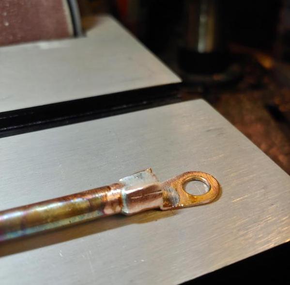
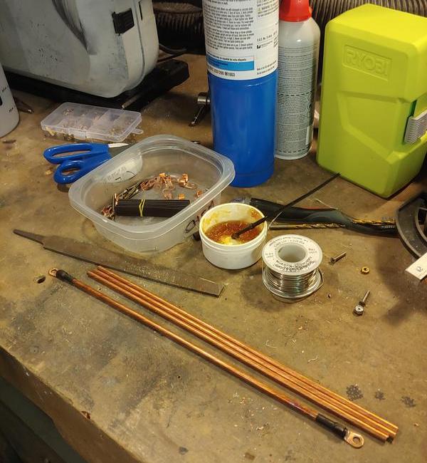
Soldering "smaller" bus bars:
CvnKsWQ.jpg

7XIlliO.jpg


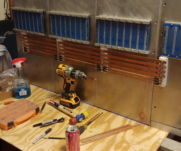
Main bus distro done:
qmoWSOD.jpg


It's been awhile since I had things hooked up and I've yet to test vu buffer strips + illumination draw, so a super rough estimate with everything pegged and energised (which of course would never happen with a mix, ever) including slots,  perhaps 1100 watts if channels kept at stock 16v +/-
For 500 slots I had to take an average from API @ 215ma per unit, and assume tube stuff and clean IC slots offset for a total of about 330watts.

Course bus bars could likely handle 10x that and not even get hot.

I'll definitely stick a kill o' watt unit between the PSU and mains when everything's done and get real answer for ya (I'm curious too).

;D Might sleep here in the winter time to save some money: 
CJ1fkVo.jpg
 
Man, this is really badass, Boji!

I keep hoing over the pics. Beginning to itch, trying to stay wise  :p
 
If you are itching to build a mixer, my advice would be to start small - 6 or 8 into 2. There is so much to learn and so many skills to acquire it is well worth scaling down to start with. You can always use the modules in the bigger when when you build it.

Cheers

Ian
 
If you are itching to build a mixer, my advice would be to start small
Thanks for the compliments guys.  If ya want to do anything big, reduce it in size until you will actually begin to take action on it.  So +1 on Ian's advice.  Make a small prototype, perhaps something that can scale up if repeated. And never work on the frame first. ;)

Edit: To mark progress, confirming ACA's work.  About to test out the ACA/Bo master fader before deciding on pcb placement. Can't believe I'm saying this, but gonna likely add a few more (shorter) bus bars under the existing ones that allow a separate, balanced power scheme for summing.  Also leaves room for the 'balanced bus' trick if it turns out there's a noise problem.
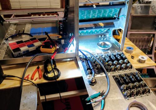
On main mix, following the advice from folks here and from Self's book, I'm attempting the 'distributed summing' approach, or two aca's per 4 channels (L&R). This leaves three, 4ch aca pcb's which is again summing down to one aca pair / st fader / st boost (CAPI's ACA/Bo).
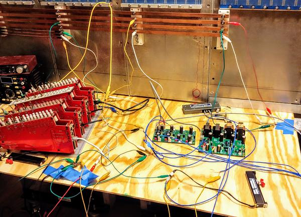
5TzZacZ.jpg


Afl and pfl won't get the same distributed treatment since a few extra dB's of noise on the monitoring bus (which is likely quite negligible, since this is only at max, a 24x2 mixer) isn't that important.

Side note: As I learned from smart folks around here, distributed summing only makes a large impact on noise when the track count is say, greater than 48 channels. So, for the 24 x 2 main mix (or even less if using the last bucket's channels as subgroups), I'll try it out and see if it nets a 2-3dB lower noise floor.  ::)
 
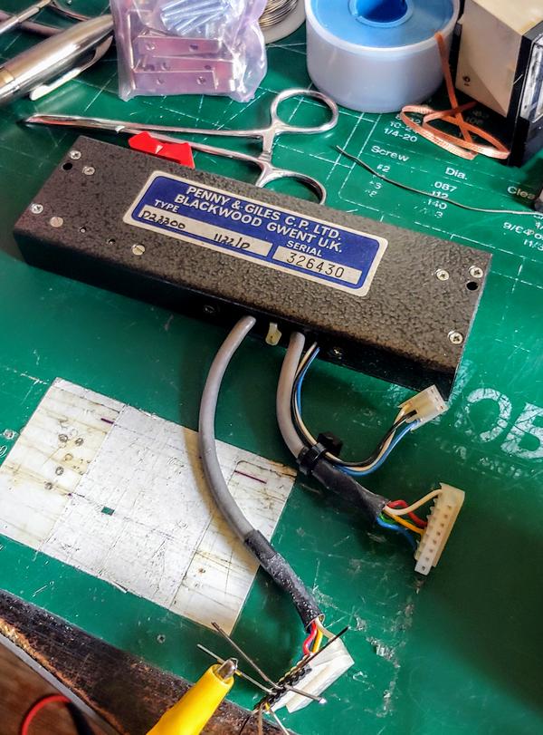
Yay, stumbled upon an older 10k P&G stereo fader didn't know I had ! It came from an old ebay sale where everything was bubble wrapped, and I missed this in the box. :) 

Has the additional bottom throw switch for true-bypass?  Perhaps it's to be used as a CV trigger in a broadcast environment.  Happy day (If it's not too worn out or scratchy).
aKNys39.jpg


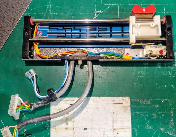
Guts:
0xWQPbW.jpg


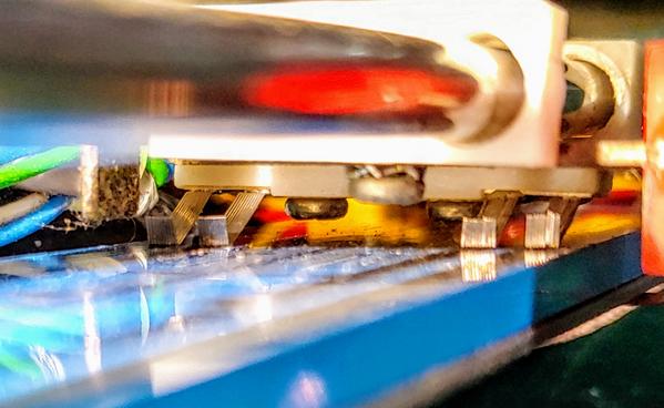
Dual (stereo) commutators? brushes. Plastic tracking holes/bushings are completely worn out.  I wonder if a replacement brush set is worth the trouble or if it would be better to simply seek out a new P&G.
XMqsMRc.jpg

 
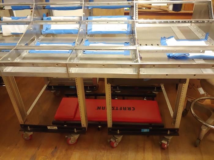
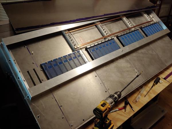
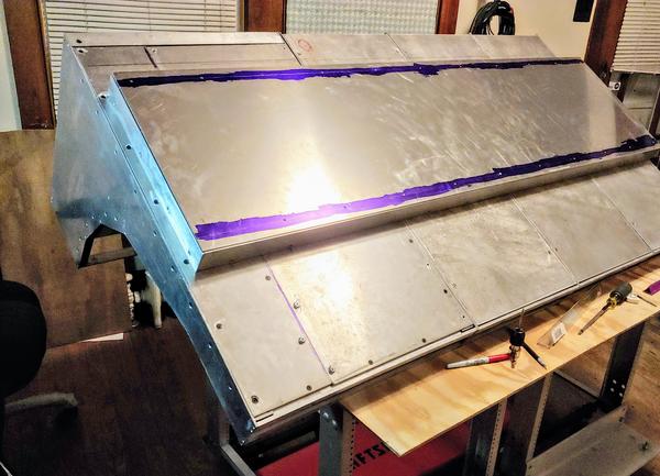
Metalwork for bus bar well is done.  Looking forward to turning this thing upright and being done with distribution. 

YzGG0Qu.jpg


fKOEwRj.jpg
 
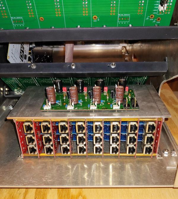
subgroup home looks great! Could you explain a little more on whats going on there?
Thanks F#, assume you mean the brick below the aca.  Basically route overkill...500 slots and A1 are treated as A/B inserts for channel or patched elsewhere. Also some extra logic for A1 when S2 drives fader. Group cards can swap 500 slot sequence.

Com terminal (mains):
QorTiFS.jpg


Ok officially have begun wiring. :)  Metalwork plate is still spinning...
0yE4k38.jpg

XeE4pVL.jpg
 
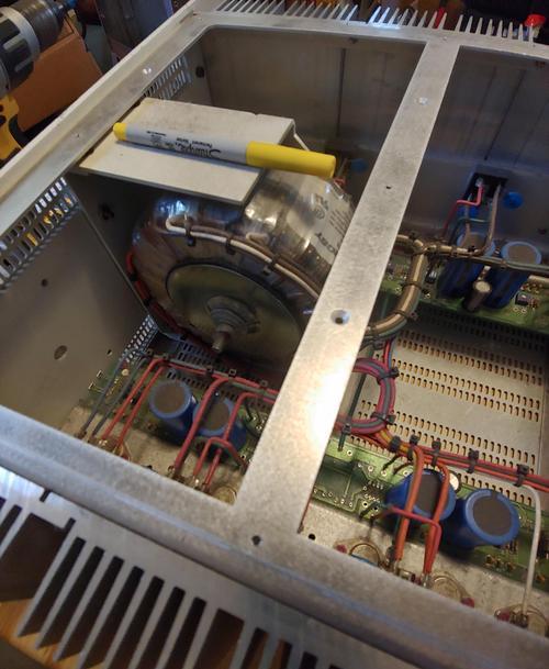
PSU trims allow volt ranges for all circuits. Should mean this passively cooled 5U beast will be all that's needed.
0aiB8YG.jpg

 
boji said:
PSU trims allow volt ranges for all circuits. Should mean this passively cooled 5U beast will be all that's needed.
0aiB8YG.jpg
No noise is good noise when mixing In a room.  Keep it quiet.
 
Com terminal for power?  On mine the com terminal is tied to the metal case but I need to look to see how pwr com is handled. I think it’s all to case of mixer.  Anyway  it’s 1976 vintage an perhaps treated differently. 

As I said in an earlier post I had to move supplies from under the console to a rack on the side to keep the transformers from inducing low level 60/120 into the buses straight above.  Having A  toroidal transformer should be better about that.  The api 605 used separate supplies with separate EI transformers per rail voltage so more inductive fields than yours. 

Amazing work boji.  I wish I had your metal working chops.
 
Com terminal for power?
Yeah, after hearing about your multiple PSU's with 8ga return runs, I figured a hefty 4ga off the AGND bus to star-ground terminal wasn't a terrible idea.  That lug will be the point where desk chassis (all the pin1's), PSU chassis, and dgnd meet as well.  Peripherals will tie to this point as well, PC, rack gear, power strips, etc. From this point a long 8ga cable will go to breaker box and tie in to earth line, which will only have a few feet to the ground rod.

Having A  toroidal transformer should be better about that.
Hope so!  This is from a broadcast desk so perhaps this was taken into consideration when building.

wish I had your metal working chops.
Thank you sir. Chops is drops multiplied by lot of flops, so I won't mind if metal working  is put to rest permanently after this thing is done!  =D

 
2nd that.  Your channel strip faceplate is very clear to read and has a world of routing possibilities with the 2 slot design.  It’s beautiful.
 
Back
Top