Damn, I guess the smarter fellas aren't going to rescue me just yet...
I suddenly realized that my second statement above was probably more likely to be misunderstood than the first. So just to clarify, my very selfish reason for doing this 990 layout is so that I can build a pair of mic preamps in the Jensen tradition for my own enjoyment. It didn't seem to me to be enough of a challenge to buy a pair of JH or TSS 990s and stick them in a box with some transformers and the usual pad, polarity and phantom switches. I mean, what's the fun in that?
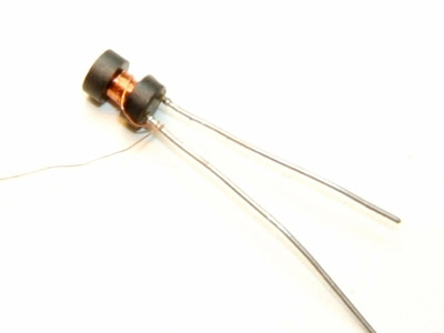
Some more thoughts about the inductor: it seems to me that one of the major goals of the unique construction of the original is meant to minimize the DC resistance so that at audible frequencies the noise voltage level at the differential stage is also at the minimum. That is the basis of the patent.
The other major consideration is that the resonant frequency of the inductor be kept high, which is why we want to keep the shunt capacitance low - to keep the resonant frequency above ft or the unity gain bandwidth of the amplifier (oops, no subscript bbcode on this forum?) and prevent instability.
But if we choose an inductor with a resonance that is above this 10 MHz figure even if it doesn't give us the 0.03 ohm resistance of the original we will still gain a benefit over not using the inductor at all, without creating any instability in the amplifier? That was a question, by the way.
If so, then there seems to be a few likely candidates that will avoid having to wind your own and find this elusive "nickle-compound" core. I mean, I don't want have to start making my own capacitors and resistors to build this thing.
Man, where has Samuel been?
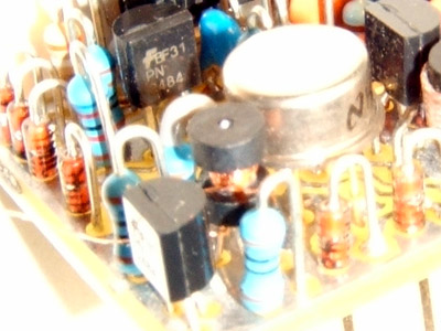
Also, someone sent me a picture of the inside of the JH990. I'm very glad that I hadn't seen them before doing my own layout and it's very clear that his was not used in the making of this Group-DIY layout. I was afraid that since they were based on exactly the same circuit they would end up looking very close but as far as I can tell they are, as they say, chalk and cheese
Edit: Upon further examination I see that the JH boards sit component side down, with long pins extending through the potting material. A very clever way to get the NPN and PNP output transistors going to the correct power pins without flipping the layout (see the other thread for an earlier version of my board with a wire link). Also, the photos I was sent were of a 990C, (which runs on multiple voltages without changing any components) not a straight JE-990 so there are a few more components on his board. That accounts for the 1/8 watt resistors and an SMD - there's barely enough room with 1/4W and no SMDs on my boards.
Ever feel like you're talking to yourself?


![Soldering Iron Kit, 120W LED Digital Advanced Solder Iron Soldering Gun kit, 110V Welding Tools, Smart Temperature Control [356℉-932℉], Extra 5pcs Tips, Auto Sleep, Temp Calibration, Orange](https://m.media-amazon.com/images/I/51sFKu9SdeL._SL500_.jpg)


