kazper
Well-known member
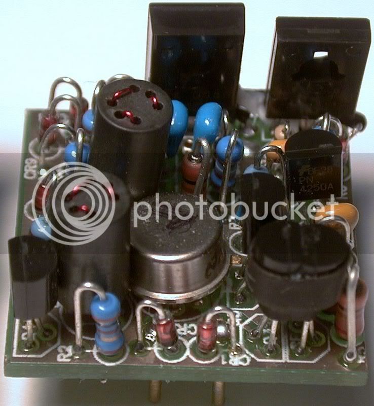
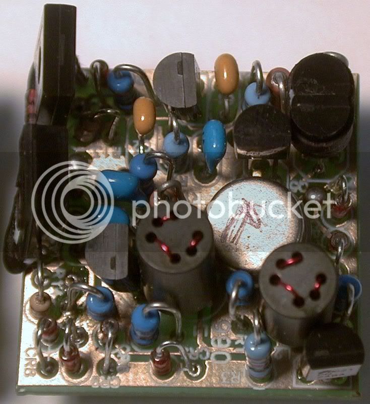
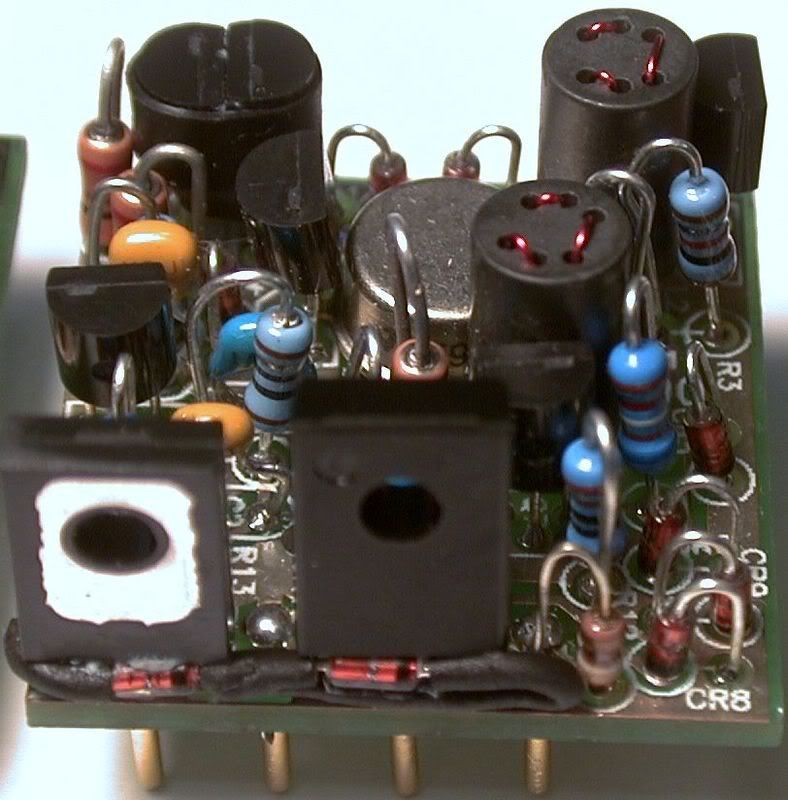
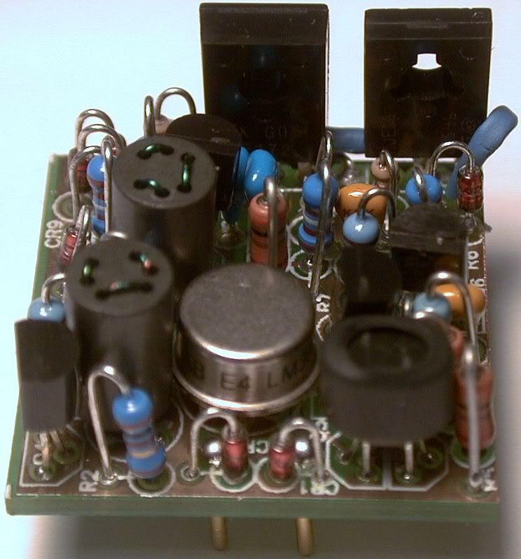
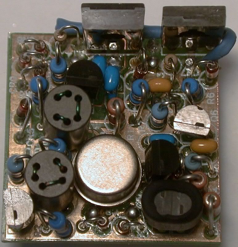
Just a few tips that I wanted to share, turn the tit on the LM394 down with a sharp pair of Needlenose or clip off. Someone else posted to install the LM394 first before Q5.
Use heat shrink to connect the Q3/CR3 together before sodering.
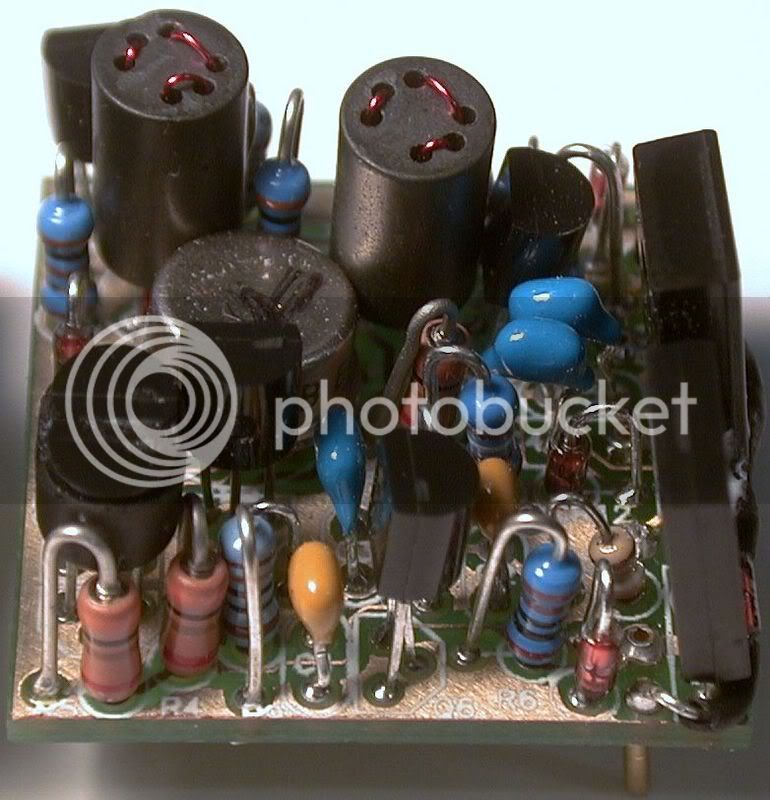
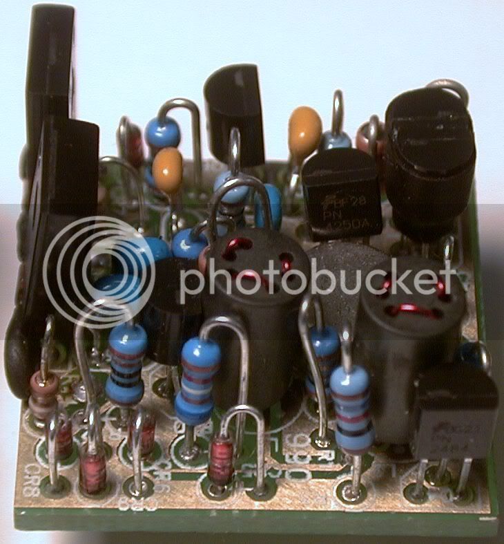
I soldered CR9,CR10 and heat shrinked them and put them through the holes on Q8 and Q9 keeping the diode in the center of the transistor. I then gently pulled the leggs into place and it seemed to look beter than trying to wrap the leg around. I then coverd it all with a larger peice of shrink and enclosed it to gether around the sides.
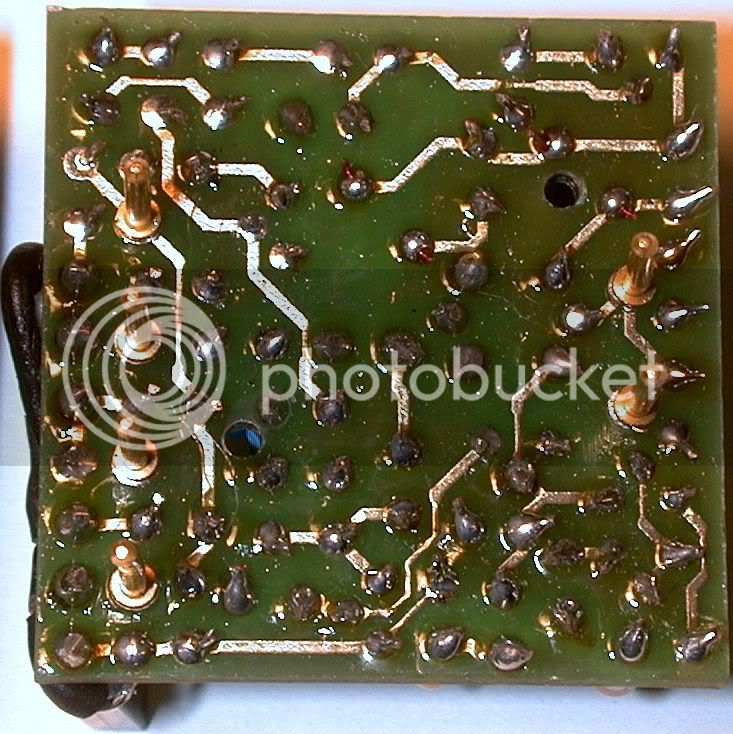
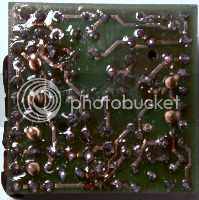
I think it would be easyer to mount the pins if they were stuck in a socket and then soldered to the board.
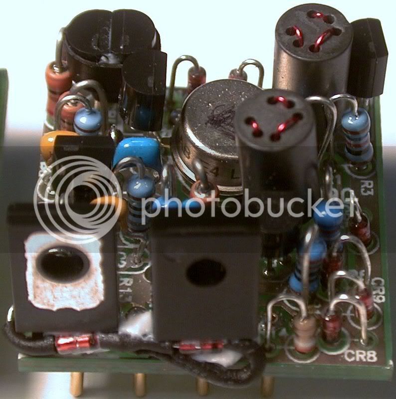
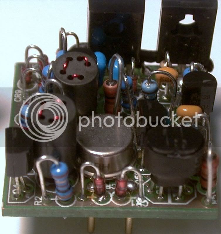
Use heat shrink to connect the Q3/CR3 together before sodering.
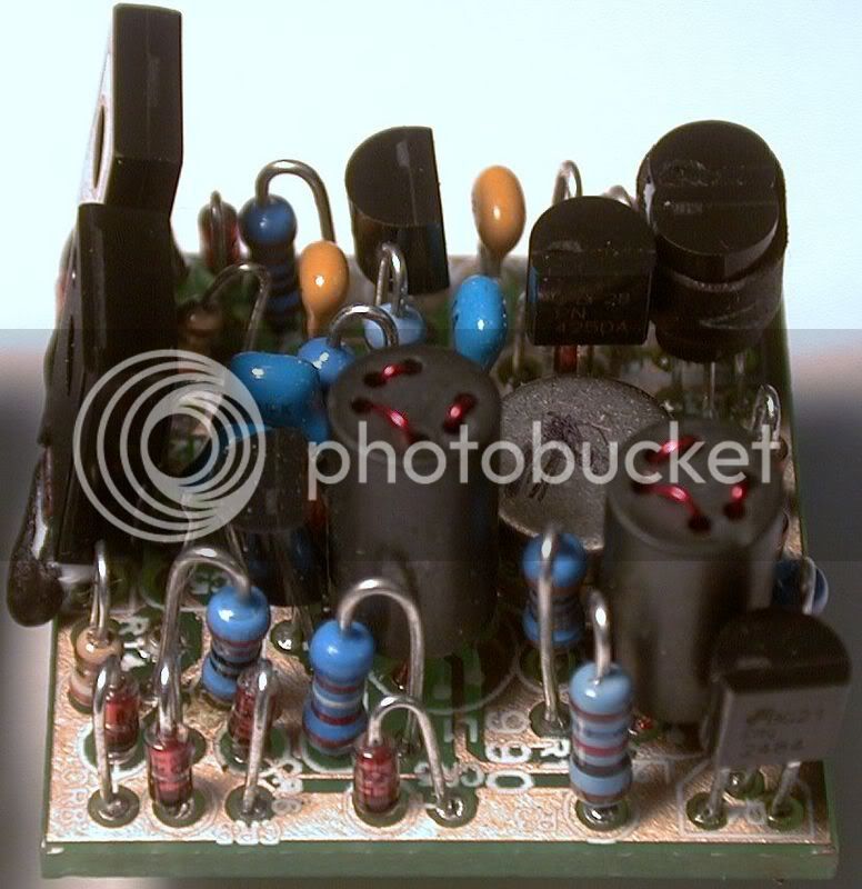
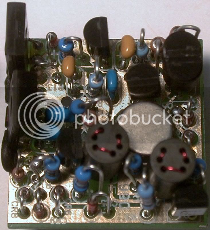
I soldered CR9,CR10 and heat shrinked them and put them through the holes on Q8 and Q9 keeping the diode in the center of the transistor. I then gently pulled the leggs into place and it seemed to look beter than trying to wrap the leg around. I then coverd it all with a larger peice of shrink and enclosed it to gether around the sides.
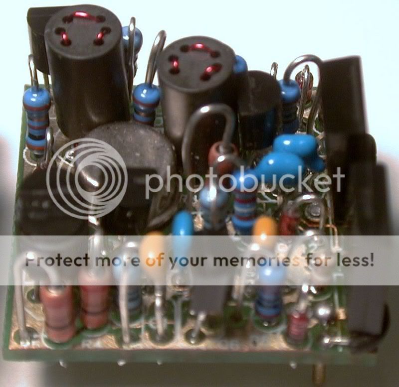
I think it would be easyer to mount the pins if they were stuck in a socket and then soldered to the board.


![Soldering Iron Kit, 120W LED Digital Advanced Solder Iron Soldering Gun kit, 110V Welding Tools, Smart Temperature Control [356℉-932℉], Extra 5pcs Tips, Auto Sleep, Temp Calibration, Orange](https://m.media-amazon.com/images/I/51sFKu9SdeL._SL500_.jpg)