You are using an out of date browser. It may not display this or other websites correctly.
You should upgrade or use an alternative browser.
You should upgrade or use an alternative browser.
DIY rotary DJ mixer
- Thread starter efinque
- Start date


Help Support GroupDIY Audio Forum:
This site may earn a commission from merchant affiliate
links, including eBay, Amazon, and others.
efinque
Well-known member
- Joined
- Jan 3, 2018
- Messages
- 393
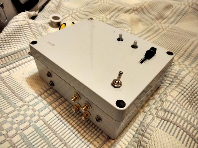
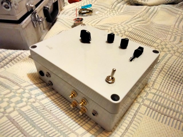
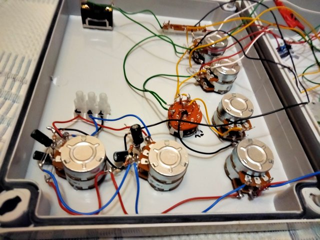
Wired the channels into the summing bus, added a headphone vol knob and a master vol :
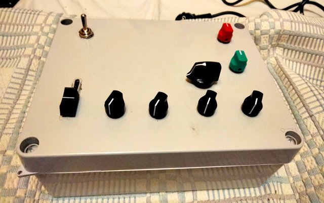
Here's a pic of the front panel :
EDIT : there's still the master EQ to do and a headphone jack plus some wiring.. other than that it's about 80% done.
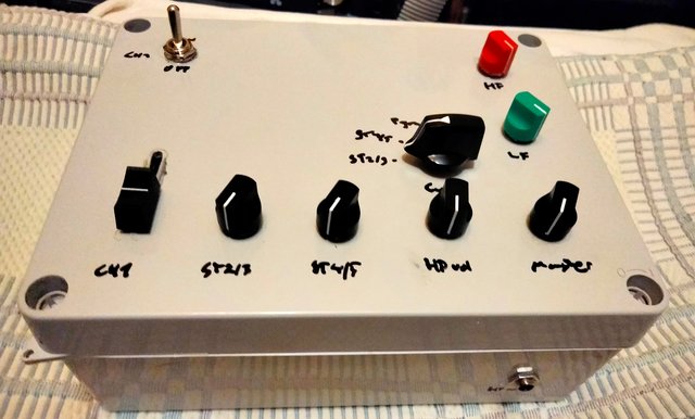
Here's a pic of the front panel :
EDIT : there's still the master EQ to do and a headphone jack plus some wiring.. other than that it's about 80% done.
Last edited:
efinque
Well-known member
- Joined
- Jan 3, 2018
- Messages
- 393
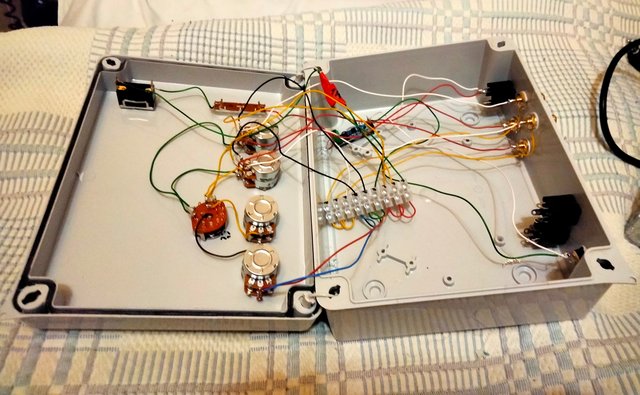
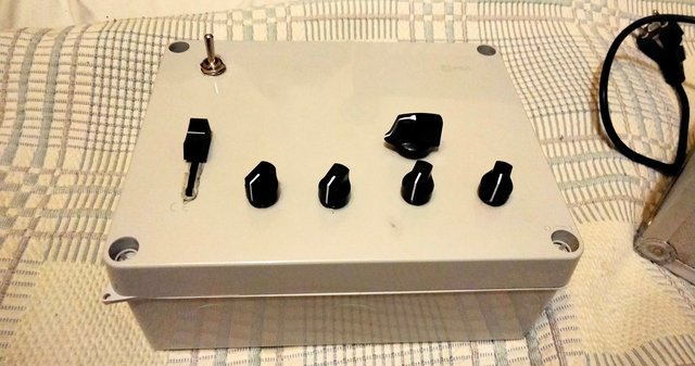
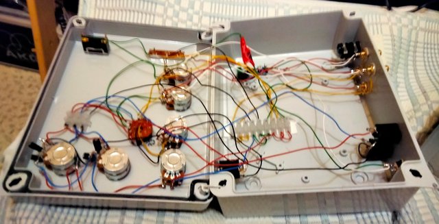
Wired a headphone out and tested both stereo channels, seems to be working.. also PFL and the EQ. The EQ sounds awesome with a crossover frequency at around 120Hz according to my calculations.
The only downside is that the 100k pots are too high resistance so only 1/4 of the taper is useable.
EDIT : there's still the main outs to wire.. other than that it's done.
The only downside is that the 100k pots are too high resistance so only 1/4 of the taper is useable.
EDIT : there's still the main outs to wire.. other than that it's done.
Last edited:


$15.98
$16.98
Gikfun Upgraded USB Mini Amplifier Electronic Transparent Stereo Speaker Box Sound Amplifier DIY Kit for Arduino EK1918
Gikfun_Official_Store


![Soldering Iron Kit, 120W LED Digital Advanced Solder Iron Soldering Gun kit, 110V Welding Tools, Smart Temperature Control [356℉-932℉], Extra 5pcs Tips, Auto Sleep, Temp Calibration, Orange](https://m.media-amazon.com/images/I/51sFKu9SdeL._SL500_.jpg)


efinque
Well-known member
- Joined
- Jan 3, 2018
- Messages
- 393
Eyeing on my next build, I measured a smartphone pgm output to be completely muted with the channel potentiometer at 57,3kOhm.. would a 10kOhm summing resistor (series) and a 50kOhm dual log pot do the trick?
I haven't measured with a CD player but I suspect they have higher output (a CDJ-800 overloaded the preamp ins of my first build).. use a 25kOhm trim perhaps?
EDIT : there's the EQ circuitry in the signal path which I didn't take into account.. I measured the HF series caps as having 290R resistance (the LF has 220R resistors) with a multimeter, is this the correct way to measure them? Iirc parallel resistance is calculated as 1/R1 + 1/R2 etc.. or ape the EQ circuitry in the new build to compensate (the input to output resistance was ~57,4kOhm)
Last edited:
Similar threads
- Replies
- 19
- Views
- 1K
- Replies
- 16
- Views
- 883