Analog signal crosstalk in DB25 and ribbon cable?

GroupDIY Audio Forum

Help Support GroupDIY Audio Forum:

This site may earn a commission from merchant affiliate links, including eBay, Amazon, and others.

oldskool1

Active member
Joined
Oct 12, 2021
Messages
39
Location
Los Angeles
I am about to build a mastering transfer console and I want to run the signals from 2 row IDC connectors on the circuit board, through flat ribbon cable, to DB-25 connectors on the back panel. These cables will be about 5 inches long.

35 years ago I built a large TTL logic circuit that didn't work at all because I had not left a ground between the data lines in the ribbon cables. I was astounded when I found 2V spikes in the adjacent data lines that caused the thing to fail miserably.

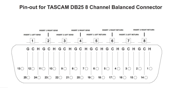
Since the ribbon cable will have signals of different channels next to each other without a ground in between, will I experience significant crosstalk between channels using this setup? Or should I wire the inside of the box with discrete shielded cables, much like how 8 channel DB-25 audio cables are made?
 
ok, after I posted the above question the forum software suggested a similar thread called "Ribbon Cables in Patchbays?". That thread has a lot of comments on the subject, including from Paul Wolff and Abby Road D'enferer, and with all this info I think I will be fine with these cables, since they have run much longer ones with no problems.

I wonder, should I just delete this thread? Since it doesn't have any new info in it? Let me know.
 
I heard a story about the tascam pinout and how basically an error had them starting on db25 pin12 vs pin 1. It was never corrected and would be foolish to do it now.
 
I heard a story about the tascam pinout and how basically an error had them starting on db25 pin12 vs pin 1. It was never corrected and would be foolish to do it now.
Correct. It's backwards.

Circuit 1 actually starts on pin 25 one pin to the left of pin 12.
Pin 12 is CH-1 cold.
There are up and down triads of pins with grounds between circuits which on the ribbon cable interleave.

Insert%20Switcher%20Breakout%20Cable%20Pinout_600.jpg
 
As ever there are many 'conditionals' to consider when trying this. for example output impedance of the 'sending' amplifier, input impedance of the receiver (not much influence), whether the signals are balanced (both active or not) and the amount of common mode rejection the receiving end can manage. Twisted pair wires can be run hundreds of metres with or without screening depending on the sources of possible interference. I(vaguely) remember making up a test jig using 2o metres or more of twisted pair multicore (a bit like CAT5 but with up to 25 pairs with overall shield) to find out how much crosstalk might be caused (ensue). but that was 45 years ago. Of course telecoms companies run miles of twisted pair wires but their threshold for crosstalk is quite high and they only use a very limited bandwidth (300Hz to 3400Hz typically). As said, the Tascam pinout has a shield between each pair but to be 'sensible' all 8 circuits should have signals of around the same nominal level (so ALL mic level or all LINE level. Twisted+flat ribbon is a cunning possibility BUT of course it runs in pairs and not triples so no good for D sub use. For short distances there should be no problems whatsoever unless you neatly clip it to a power transformer or unshielded high level audio transformer.
 
Back
Top