ECL84 tube as mufollower?

GroupDIY Audio Forum

Help Support GroupDIY Audio Forum:

This site may earn a commission from merchant affiliate links, including eBay, Amazon, and others.

rafafredd

Well-known member
Joined
Jun 3, 2004
Messages
2,412
Location
Rio, Brazil
I have many ecl84 tubes and I would like to know if you think it would work ok in the following aplications:

http://www.svetlana.com/graphics/TB/No10.fig1.gif
http://www.svetlana.com/graphics/TB/No10fig3.gif

The schems was originally for the ECL82, but I think the ecl84 will work ok. I just thought I would ask before I build the thing.

Also, I´m almost sure it would work better in the second schematic, as a mu-follower.

If it works I will make little single tube micamps/lineamps with transformerless and lowZ outputs (<1000ohms, according to the schems). As I have many many many, it could be nice for a 8-16 channel tube mixer.

Thanks!
 
> if you think it would work ok

IMHO: these types of gimicky tube-schemes are not OK. Oh, it will "work OK", output is bigger than input, but not better than old reliable layouts.
 
:oops:

Thanks for your valuable opinion, PRR.

I really expected I could do something good with this, but it seems that this is actually worthless...
 
> actually worthless...

I didn't say that.

But look at No10fig3.gif. At a 450V supply, distortion is rising badly at 15V-20V. This is not great performance for this supply and complexity.

Moreover, this is in 100K load. The 1000Ω output impedance does not mean it will drive 1KΩ.... most negative feedback amps won't drive a load similar to their output impedance (and this is sure a feedback amp).

If you did hang 600Ω off the output, gain would fall badly. See, the first stage plate load is bootstrapped by the second stage cathode. That is how the unloaded gain approaches Mu: the first stage works very hi-Z load. But when you load the cathode follower its gain drops from 0.95 to 0.2, the first stage dynamic load drops from 200K to 20K, gain falls and distortion rises.

Where both tubes carry the same current, there can be some small push-pull distortion cancellation. In this case, the 18K resistor (25W!) forces the second stage to act single-ended.

If you did a simple resistance-coupled gain stage and cathode follower, no trickery, performance would be similar no-load and probably better in low-Z load. Driving 600Ω directly, any tube strains, and needs large current to drive high levels. But I think a plain cathode follower will do better than this baffling design.

John Broski has an interesting analysis of stages like this.

Heater-cathode insulation is also an issue. I shudder to think of putting 700V on this common-heater stage, as suggested.

Also of course: no Balanced output. If you care.

That '84/6DX8 is an interesting tube, and might work very well as two plate-loaded stages with feedback to the first cathode. Most twin-tubes won't work so well this way, because the output tube can't spare enough current to boff the input cathode. This might. And a pentode does no worse when driving low-Z loads (unlike a triode, which loves hi-Z loading).
 
Thanks on more time for the comments, PRR.

I think I´ll try to draw my own amp. Probably I´ll end up with two plate followers stages.

But... Do you know what tubes does the parts of the ECL84 match?

Like what´s the tube type that is close in characteristics with the triode part of the ECL84?

And whta´s the tube type that is close to the pentode part in a ECL84?

This would make it all a lot easier for me. Thanks.
 
You won't get enough gain for a mic preamp with a single hi-mu triode coupled to a cathode follower. And like PRR, I don't like those gimmicky "mu follower" designs when in comes to driving real-world, outside-the-box loads.

Rather, I would use this tube with the triode stage as a common cathode input amplifier, R-C coupled to the pentode stage, pentode plate transformer-coupled to the load with feedback from pentode plate to triode cathode. Open-loop gain would be pretty high, which would allow for an appropriate amount of negative feedback.

Most single-ended output transformers that would be suitable for this tube are designed to couple to loudspeakers, though, so you might need to get something custom-made. Didn't you say you have a friend there in Brazil who manufactures custom gapped output transformers?
 
> what tubes does the parts of the ECL84 match?

The triode smells like a 12AT7, though maybe a little bigger.

The pentode is the standard video amplifier from late tube-TVs. It is roughly like the output tube in a kitchen radio, except much higher transconductance, softer plate resistance, and much less linear than an "audio" tube.

And TV tubes were generally tuned to work well at lower supply voltages, so I'd think about 200V-250V. This means cheaper caps and lower transformer impedances.

Assuming a mike input transformer, I'd bias the triode with a 100K or 220K plate resistor and trim the cathode resistor to get the plate voltage about 2/3rds of the supply voltage. That's always a good starting point for small triode voltage-amps. Voltage gain will be around 2/3rds of Mu, or about 40.

The output tube... well, you could do a lot of experimenting, but I bet it works OK at the book-value conditions. About 200V supply, transformer or low-value resistor load, about 15mA-20mA plate current. It won't have the voltage swing of a good audio tube, so I'd expect about 100V swing from a 200V power rail. At max-output it could swing 15mA-20mA peak. It will be more linear with less current swing.

Taking 100V and 15mA peak, we need 6.7K load and get 750 milliWatts out. At 100V and 10mA peak we use 10K load for 500mW out. So we are in the +27dBm range at clipping and can probably get well over +18dBm clean.

We could instead bias at 20mA and use a 600Ω resistor DC load. Peak output voltage is 20mA*600Ω or 12V peak, 8.4V RMS. If we add an AC load of 600Ω these numbers are half: 4.2V RMS, +14dBm. A 3K resistor load will make a little more output in 600Ω, maybe +18dBm, but the gain will vary a LOT with load resistance and the sound will vary.

The output gain is roughly Rl*Gm. Gm is roughly 1/100Ω. For 10K transformer, Rp is significant, so the gain at the primary is more like 6K/100Ω or 60. A 10K:600Ω transformer is 4:1, so stage gain to load is 15. For resistance coupling, gain is like 300Ω/100Ω or 3 into a 600Ω load.

While a transformer is expensive, it gives much higher gain, floating output, and avoids a large high-volt output cap. So I'll steer you that way.

With input transformer gain of 1:10, 1st stage gain about 40, second stage gain to 600Ω of about 15, we have total gain of 10*40*15= 6,000 or 75dB. The non-linearity of that video-output tube suggests a hunk of feedback, maybe 20dB. So 55dB gain is easy and clean, 60dB gain won't suck.

Without the transformer, distortion is about twice as high due to poor loading, and about 5 times higher due to less feedback, and much higher above about +10dBm due to just running out of current.

If you are sure your loads will ALWAYS be over about 5K, resistance coupling looks better.
 
Thanks for all the details, PRR.

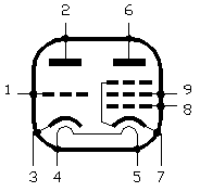
I was just wondering... If I strap the pentode as a triode will I have a better performance?

There´s two ways of making this a triode, I can join 9 and 6 for a plate or 9 and 8 for a grid.

ECL84.gif
 
> If I strap the pentode as a triode will I have a better performance?

Depends on the circuit.

In the conventional triode-strap, G2 to Plate, I would expect Mu to be around 20 (unless you can find an actual spec). At around 18mA, the transconductance is like 1/100Ω, so the plate resistance is around 2,000Ω. That's a great value for driving a 5K or 10K load. If you suck it down with 1K or 600Ω, distortion will be similar to the pentode mode.
 

Latest posts

Back
Top