Electrical problem: 120V between GND's (FIXED!)

GroupDIY Audio Forum

Help Support GroupDIY Audio Forum:

This site may earn a commission from merchant affiliate links, including eBay, Amazon, and others.
> Now I don't measure 120V between my two grounds in the different outlets anymore.

Good, but......

> ground was left floating at this point. White/black on that 2-wire were swapped (white=hot, black=neutral).

The 3-light tester "should" have flagged this "open ground".

(It could not also know of the white/black swap; no reference.)

So why was the 3-lite saying "OK!"?? There's many things it won't diagnose, but an open ground is drop-dead easy.

I have a bad feeling there is a white-ground short somewhere. That's something the 3-lite can't sense; indeed it can only be found by inspection, gross abuse (pull line current and see if ground rises), or with fancy sensing (the new arc-fault breakers required for bedrooms circuits are finding lots of such faults).

> the attic ground connects up to neutral in the junction box where the 2-wire terminates in the attic.

NO! That is NOT legal per NEC!! White and ground shall meet ONLY at the "service entrance", generally the main fusebox.


For the EXACT reason you saw. Faults which make White "live" are sorta-benign, but live-White which also makes Appliance Case "hot" is deadly.

He's shut-up your 3-lite, and momentarily eliminated the shocks. If the old cloth cable were in PERFECT shape and carefully watched, it might be "safe enough". But the cable is old and the junctioning is dubious.

(Which of your two "main fuseboxes" is MAIN is an interesting question.).


> ground wire should follow the same path back to the panel as the Hot and Neutral.

That's customary and normal and best. I'm not sure it is *required* under NEC. (Altho an exposed ground wire must be fat to resist mechanical damage.)

As you say, loop-area is bad for audio and some gigantic transients (lightning induction).

There are indeed layers of problems. First: family and pet deaths and injury. Second, killing mini-plugs may be justifiable but should be done with hammer and fire, not loose electricity. Finally, clean quiet environment for audio work. Landlords can be yelled-at for the first, requested for the second, but generic rental space does not assure clean audio (that's what $$$/hour studio space is for).

Where's your rig? Attic? How big/hot? Not? Big radio stations? Then get a 24-outlet power strip, put EVERYthing on that, and don't go near lights or radiators. I did hundreds of gigs on 2-pin ungrounded power. It's OK as long as everything references each other.
 
I'm having a hard time following this, but it sounds like you just said that your attic "ground" is connected to the white neutral wire in a junction box. If by this you mean that the attic is wired with romex with ground and has 3 prong receptacles, then YOU'RE NOT DONE YET! You fixed the reverse polarity but still have a broken ground.

You will need to either connect your attic ground to the house safety ground somewhere NOT TO THE NEUTRAL, or install 2 wire outlets in the attic (if that option is legal in your area for remodel work).

You need to get a competent licensed electrician in there, not one who will tie a ground wire to neutral in a junction box and call it good.

As PRR says, the neutral and ground must be connected ("bonded") together at one point and only one point, which is at or near the service entrance. Check the current code for up-to-date requirements, don't trust me or anyone else on the internet please. Your double service may have some special requirement for neutral bonding and ground rod connections as well.

Cheers,

Michael

PS THe NEC rules for grounding in Article 250 of the code are designed so that it is very unlikely that any single fault would introduce the dangerous situation you had earlier with an energized ground. Your current attic situation is currently not protected from a class of faults which would require the neutral conductor reliably carry ground fault current all the way back to the panel. The grounding conductor is required to be continuous so that it can more reliably carry the fault currents back to the neutral bonding point at the service or breaker box. The neutral conductor is not wired in the same way.

With your current situation, any equipment or wiring faults that short the hot (black) to ground would carry the fault current on the neutral, possibly causing an open circuit through an unreliable connection.

PPS The silver color on the sheath of the old style NM cable (not all "Romex") is not a conductor. NM stands for "Non Metallic" sheathed cable.
 
Welcome to the world of dodgy wiring...

I would second PRRs suggestion to use one or several power strips to keep all your studio gear on the same page and I'd be tempted to carry that one step further and suggest a power strip with a GFI  http://www.nextag.com/gfci-power-strip/stores-html

Maybe even pick up a few and use them in bathroom and kitchen areas where humans may get inadvertently grounded to earth, through plumbing.

If this was your house, put in GFI outlets in risky areas and maybe pull some new wire up to the attic, but we're talking time and money to make this wonderful, that neither you nor your landlord want to spend.

JR
 
> rules for grounding in Article 250 of the code are designed so that it is very unlikely that any single fault would introduce the dangerous situation you had earlier with an energized ground

Well said.

I warn lurkers that Art 250 is like Torah: pre-education and annotation may be needed.

> The grounding conductor is required to be continuous so that it can more reliably carry the fault currents .... The neutral conductor is not wired in the same way.

There are restrictions on splices in ground, but not for this case.

Examples: well-screwed conduit is a fairly good safety ground despite being jointed 2 or 4 times on every run between boxes. Common NMC cable can't be run past the first device without splicing ground. (There are even special green wirenuts... not that they work better, but they allow simpler ground-splicing.)

AFAIK (IANAE) ground can never be wired-through a device, as power can be. Removal of a device should not even suggest a break in ground. This often means a fat wire-nut pigtailed to the device.

Ground conductors for the MAIN grounding electrodes and for hot-tubs have stricter restrictions on splices. He should not be fooling with main grounds, and a hot-tub in the attic raises many issues.

> YOU'RE NOT DONE YET!

As a life-safety thing, this situation could fall under NEC Art. 406.3(D)(3), which allows use of a GFI where groundING circuits connect to UN-grounding wiring and no practical way to run an honest green back to the service entrance.

I'd say if jonathan dies, he has a good lawsuit against the landlord, electrician, and town. You expect jackleg work from landlords. Electricians are (should be) trained and licensed and should decline jackleg solutions. The fact that this one may have omitted even a $20 GFI suggests the town is known to be slack.

Actually, the NEC per se is not law anywhere, until the local government Adopts it. Some cities have self-written codes. And my town did not adopt any building code until a few years ago (my garage is not too different from your attic). So it may be perfectly OK to kill tenants. Then it comes down to protecting your own butt 'cuz nobody else will.

GFI makes electrocution far less likely but does nothing to drain stray EMF off the audio gear and interconnects. As said, this is often acceptable.

 
Reading the NEC rulebook is always a painful experience (now NEC 2011 will start popping up in some jurisdictions) . Each Article refers to other Articles which in turn refer to even more Articles.  The rules authority "Mike Holt" has published many books and even more magazine articles on NEC rules applications.  His words and many drawings make understanding this difficult subject much easier.
 
PRR said:
Where's your rig? Attic? How big/hot? Not? Big radio stations? Then get a 24-outlet power strip, put EVERYthing on that, and don't go near lights or radiators. I did hundreds of gigs on 2-pin ungrounded power. It's OK as long as everything references each other.


Yes, back to how this relates to audio and grounding one's studio and gear (others may be in a similar situation).

I am about to install 4x 96 point remote-patchbays. I've got a handful of DIY pieces with several more in the immediate pipeline and even more in the to-think-about-pipeline. Basically a console-furniture-desk with about 45 RU of space, a three-bay rack with 36 RU total, and a couple 20 RU racks. In other words, significant number of discrete audio I/O's and chassis GND's connecting back up together. At this point I am concerned about gnd noise of course but the mental image of 120V in this GND path is very illustrative. I mean the 120V is the same thing as typical GND currents/noise. It's just "signal" (although understood that it can be deadly signal)

Up here in the attic I have two circuits/branches from the breaker box in the crawlspace/basement.

1. One of the circuits comes up between some walls towards the middle of the house. That branch is three wire romex all the way back to the breaker and wired correctly.
2. The second branch/circuit that comes up here is two wire romex from the breaker box that terminates into a junction box above our front foyer. From there the branch fans out to the various wall outlets & ceiling fixtures using three wire romex. GND and NEUTRAL are bonded (twist-nut) in this junction box where they return to the breaker panel on one wire.

Not going to argue NEC code and if it was my house I would just pull some 3-wire romex down to the panel (although there is plenty of that 2-wire cloth romex down there). Neutral and GND are bonded at the panel(s) and in the crawlspace to building copper.

So, two circuits in this room and the path to GND (Chassis-GND on all the audio gear) on those two circuits is slightly different; ie; impedance to GND is going to be different based on which circuit that gear is plugged into.

General rules? Pro's Con's? Electrical wiring and building GND situation may not be optimal but at least we understand it and it has been quantified to a certain extent. How best to approach significant studio wiring with the knowledge developed up to this point.

  • Connect audio GND (pin1) @ source equipment and disconnect at destination equipment. Patchbay does not bus ground but patches it through.


  • DISConnect audio GND (pin1) @ source equipment and connect at destination equipment. Patchbay does not bus ground but patches it through.


  • Connect audio GND (pin1) @ both source and destination gear and disconnect at the patchbay.


  • Disconnect audio GND (pin1) @ all source and destination gear, connect audio GND at patchbay. Patchbay does bus GND's together and is connected up to building gnd. ie; all gear references chassis gnd but audio is floating at the equipment i/o's. I can get a spool of fat GND wire and run that down to cold-water-copper from the patchbay.

Some of these approaches have unique wiring/cabling schemes. Wouldn't it really be best to just have all your audio cables "be-the-same"? That makes it easy to buy cables as needed and even make cables as needed without having to think about it (ie; designed for minimal mistakes in implementation).

Of course this situation will have "guest" equipment and "loner" gear connecting up, not to mention additions of more gear.

Answer:
Connect/test/measure/modify.
rinse/repeat.

Thoughts / Recommendations / Comments / Concerns ?

Best,
jonathan
 
If you have a real ground on one branch that is the obvious one to use.

Any products that use 2 wire line cords can be plugged into the 2 wire branch.

Grounding rigor for audio paths is always the same. XLR pin 1 to ground all the time at all ends. If you have a piece of gear that can't hack that maybe use this as an opportunity to fix the gear (search pin 1 problem), unless it is some esoteric antique you don't want to alter for resale purposes.

I will repeat my suggestion to consider GFI outlet strips in light of your experience. I am almost tempted to grab the good ground from the other branch to ground bond your 2 circuit outlets, but that's probably not to NEC.

JR
 
JohnRoberts said:
Grounding rigor for audio paths is always the same. XLR pin 1 to ground all the time at all ends. If you have a piece of gear that can't hack that maybe use this as an opportunity to fix the gear (search pin 1 problem), unless it is some esoteric antique you don't want to alter for resale purposes.

RE: Pin 1 Problem

I found a reference that refers to ground currents outside of the chassis as the fox and inside the chassis as the hen-house. We obviously do not want the fox in the hen-house so the pin-1 get's connected the chassis along with the "building/outlet-ground".

Same idea with a house/facility except the "chassis" is the dirt and the audio/electricity coming into the house is center-tapped and also earthed at the pole/service-entrance.

-j
 
Not "arguing code" here. Your connection with the ground and neutral of a 3 wire circuit connected to the neutral of a 2 wire feeder is a bad idea, illegal, and unsafe. That circuit has no ground and what's worse, if a fault develops it could energize the parts that are pretending to be ground. A GFI alone will not fix the problem. You need either 2 wire outlets on the circuit fed by a 2 wire feeder or to properly ground the 3 wire circuit with a 3 wire feeder with ground.
 
0dbfs said:
JohnRoberts said:
Grounding rigor for audio paths is always the same. XLR pin 1 to ground all the time at all ends. If you have a piece of gear that can't hack that maybe use this as an opportunity to fix the gear (search pin 1 problem), unless it is some esoteric antique you don't want to alter for resale purposes.

RE: Pin 1 Problem

I found a reference that refers to ground currents outside of the chassis as the fox and inside the chassis as the hen-house. We obviously do not want the fox in the hen-house so the pin-1 get's connected the chassis along with the "building/outlet-ground".

Same idea with a house/facility except the "chassis" is the dirt and the audio/electricity coming into the house is center-tapped and also earthed at the pole/service-entrance.

-j

I think I raised this point earlier in this thread, namely neutral corruption of grounds, pretty much insures a dirty ground.

Well designed Pin 1 tolerant gear should ignore even that, but your house demonstrates some of the kind of nonsense people encounter in live sound with sketchy mains power.

I am reluctant to suggest this, but I would personally be tempted to do a little Rube Goldberg outlet box where a three circuit outlet, grabs the hot and neutral from your two wire branch and the real ground from your 3 wire branch. This is probably not OK with NEC because the ground wire is only sized to handle the fault current from one branch, but I suspect this is a lesser evil than throwing neutral and grounds together through your studio audio wiring.

This indeed would justify being called "dangerous" audio... and not for the faint of heart.

If you want to do it right pull another 3 circuit branch, but even then your audio gear could be across two different grounds and arguably an actual loop (most problems called ground loops are really from currents flowing in a common conductor, not intercepting a magnetic field with a loop area).

This is about the third time so I should stop repeating myself, but don't discount the ability of GFIs to prevent injury. Can you even buy 2 circuit outlets anymore?

JR
 
JohnRoberts said:
0dbfs said:
JohnRoberts said:
Grounding rigor for audio paths is always the same. XLR pin 1 to ground all the time at all ends. If you have a piece of gear that can't hack that maybe use this as an opportunity to fix the gear (search pin 1 problem), unless it is some esoteric antique you don't want to alter for resale purposes.

RE: Pin 1 Problem

I found a reference that refers to ground currents outside of the chassis as the fox and inside the chassis as the hen-house. We obviously do not want the fox in the hen-house so the pin-1 get's connected the chassis along with the "building/outlet-ground".

Same idea with a house/facility except the "chassis" is the dirt and the audio/electricity coming into the house is center-tapped and also earthed at the pole/service-entrance.

-j

I think I raised this point earlier in this thread, namely neutral corruption of grounds, pretty much insures a dirty ground.

Well designed Pin 1 tolerant gear should ignore even that, but your house demonstrates some of the kind of nonsense people encounter in live sound with sketchy mains power.

I am reluctant to suggest this, but I would personally be tempted to do a little Rube Goldberg outlet box where a three circuit outlet, grabs the hot and neutral from your two wire branch and the real ground from your 3 wire branch. This is probably not OK with NEC because the ground wire is only sized to handle the fault current from one branch, but I suspect this is a lesser evil than throwing neutral and grounds together through your studio audio wiring.

This indeed would justify being called "dangerous" audio... and not for the faint of heart.

If you want to do it right pull another 3 circuit branch, but even then your audio gear could be across two different grounds and arguably an actual loop (most problems called ground loops are really from currents flowing in a common conductor, not intercepting a magnetic field with a loop area).

This is about the third time so I should stop repeating myself, but don't discount the ability of GFIs to prevent injury. Can you even buy 2 circuit outlets anymore?

JR

Ok. I'll get either a GFI outlet or strip for those. Thanks for the prodding. Feeling better about that now? I am so thanks again.

Yes. I can get a box of romex and just pull a new 3-wire to the breaker panel. I might just do that since it's easy and getting an electrician back out on my landlords dime would be not-easy. Of course, I could pay an electrician but then we're not talking about something that is hard to do since the original fault has been identified/localized. I think I have a box of romex at our other house that I can grab when we are back there again to get this done. My pay-it-forward goodwill to out landlord.

But yes, I can try to keep all the studio electrical on one outlet/source but the reality is that rack location requirements will prevent this from being practical so I need to make it work best with different outlets. Now, once I get it all connected up and there are issues I can go from there but I've already had it connected up with no issue. Except o course for the 120V. ha!

Plus, this is a "mix-room" but when I connect up a snake leading into our downstairs living room (or whatever) for the odd tracking session I will no doubt have different electrical circuits involved in each location with grounds connected and the various chassis exposed. e.g. 48V mic's, tube-mic's, guitar-strings/amps, headphone amps, etc.

Thoughts about busing all patchbay grounds together and running a dedicated thick GND wire directly to the building service GND/copper? If I am running the romex I can probably run that wire at the same time easily enough and since all audio GND's will terminate at the PB would a dedicated low impedance audio GND be significantly helpful?

Best,
j
 
If the audio hardware treats pin 1 properly, and differentially subtracts the audio from whatever odd ground voltage is present at whatever pin 1, there is no need for brute force ground treatments.

Trust the force (of differential amplifiers) Luke....

JR
 
My thoughts on AC power:
In the distant past, in a wood frame room that had no exposed water pipes or other metal items connected to ground, it was OK to use a two wire AC power line for A/V equipment. But now most systems are connected to satellite or cable or telephone sources it's no longer safe.
In any case,  I would connect all my equipment to one circuit, with the possable exception of very large power amplifiers.

My thoughts on XLR pin #1:
I would always connect output pins #1.
Bill Whitlock and Tony Waldron have different viewpoints on input pins #1.  Tony writes - always connect input pin #1.  Bill writes that a hybrid input connection is OK.
 
And JR's viewpoint on pin 1 is to always bond it to ground (with properly designed gear).

There may be some subtle benefit from steering shield noise currents into one of the two chassis with added compliance in series with one of the two pin 1s, but any compliance there also raises the potential level of shield noise voltage that can then couple into the audio path and must be rejected by the connected differential circuitry. 

Pick your poison.

JR
 
> 4x 96 point remote-patchbays. ...DIY pieces ....a console-furniture-desk ...45 RU of space, ...rack with 36 RU ...couple 20 RU racks. In other words, significant number

SIGNIFICANT audio investment.

Significant electrical load.

45+36+20+20= 120 rack spaces. Figure 2/3rd full? 80 rack units. Figure most stuff is 10 Watts per rack space, but cheap/small transformers may draw 20VA to deliver 10Watts. 80*20VA is 1,600VA. Plus say 2x150W monitor amp, 600VA. Plus PC/Mac, 300VA. Plus say a Fender Twin, 250VA. 2,750VA. 23 Amperes at 120V. Plus light, 500-1000 watts incandescent, 150W-300W fluorescent if you can stand the color/flicker.

You got over ten thousand dollars of gear. As you know, bogus electricity will burn gear. Yesterday a $5 mini-cord. Tomorrow, maybe the guts of a vintage Telefunken or some hard-wrought DIY gear.

IMHO: don't dink-around, don't short-cut.

Pull one fresh 12/3-G (Red, Black, White, Green) up from the least-ugly fusebox to your space (split 240V). Be SURE you take opposite "phases" for the Hots (should be 240V between breaker screws) so the "neutral" is a True Neutral. (A 2-pole breaker may not be required but is wise; IIRC under modern Code it IS required for a split-240.) Split as two 20A 3-wire (Black, White, Green) circuits. Put a duplex every 10 feet around the walls, biased to where you need them. WireMold is handy for such work. Metal for headbanger rooms, plastic for civilized spaces.

Abandon ALL other outlets up there. (Or put lights on them.)

> snake leading into our downstairs ...for the odd tracking session

Then tap both sides of that 12/3-G and splatter a few outlets in your chosen tracking room. Don't let your trackees plug into the legacy outlets (show your burnt plug and tell the tale), make them use the new outlets (lay 2x4-way outlet cords where they set-up).

Yes, all this may cost a thousand bucks or more, between Electrician and sweat-labor. To me, that sounds like a lot of money. (I'm saving for $110 to wire the garage.) But you have LARGE investment in gear which is at the mercy of electricity. When I found a similar situation in my office at school, I gripped and moaned and committed $3,234 to proper wiring (school contracts get over-charged for the over-overhead).
 
Hi PRR,

I've been thinking about your last comment here for a while now and this sounds like a really very good idea to me on a couple levels.

I'll have to look into parts and things but I am envisioning a "dog-house" type of contraption where I could take a couple 20A feeds (split-110/220, like you mentioned) directly from the breaker. Dog-house has a twist lock or two (rated appropriately) that I can then extend to wherever I need it and uninstall when done.

Can probably add a meter or two and maybe even some filtering to the doghouse to make it even more-cool.

Great for temp or rental housing, guerrilla-tracking-sessions, remotes, backwoods-generator-gig's, etc...

Cheers,
j
 
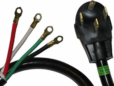
Consider wiring up to proper 4 circuit 240V outlet  (Dryer.. hot-hot-neutral-ground) 
4prongplugwire.jpg

Then plug your removable 2x 120V distro into that with a dryer plug.

or not...

JR

 
Back
Top