EQN build thread

GroupDIY Audio Forum

Help Support GroupDIY Audio Forum:

This site may earn a commission from merchant affiliate links, including eBay, Amazon, and others.
peter purpose said:
I'll get an abortion of a schematic up...... I've been avoiding it like the plague.
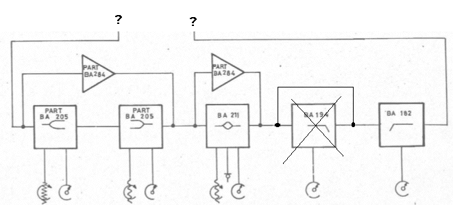
peter, just wondering if you had a chance to draw up a schem? especially everything outside of this:
ppeqnquestion.gif


I am trying to figure out a way to go into the EQ directly from an EZ1290......
 
Anyone devise a value for R29 with Ed's tx?

I don't even know where to start trying to figure it out myself. Any leads would be appreciated.

Thanks.

 
i think in an earlier post in this thread peter said R29 would be in the 600 to 1.2kohm range.  i'd guess you can safely plug in a 1k for now to get it working.

ed
 
Hey Ed, thanks

Yeah, I was going to just do that to make sure everything's working, but I'm not sure how to determine what the best value would be. Obviously not a hurry of any sort.

 
i still dont know how to attach the pins to the grayhills...

setup for sw6 (example): front view, one pin attached most northern, then turning the switch ccw and then attaching the second pin most southern.

is this the correct?
 
Brizco said:
i still dont know how to attach the pins to the grayhills...

setup for sw6 (example): front view, one pin attached most northern, then turning the switch ccw and then attaching the second pin most southern.

is this the correct?

Sort of. Have you read the instructions that come with the switch?
I'll stick up a pic of pin positions when my camera is charged.
 
briomusic said:
peter, just wondering if you had a chance to draw up a schem? especially everything outside of this:
ppeqnquestion.gif


I am trying to figure out a way to go into the EQ directly from an EZ1290......

Very rough schem, but should help.

84rough.jpg
 
Sort of. Have you read the instructions that come with the switch?
I'll stick up a pic of pin positions when my camera is charged.

i read the datasheet of the rotary switches, but i wasn't lucky finding something. or my english is too bad...

a pic would be very helpful!
thanks a lot!!
 
Hi,

About the pin position of the switch take a resistor, and try all holes one by one till you got the action of the switch you need, only twelve holes, so the job is not to time consuming.

DJN

 
Anyone using this with a standard API rack yet? I'm getting +/- 16v into the Lamda DC converter, however I'm getting +6v on every pin on the way out. No power further down the line either. Any ideas? I'm looking at the Lamda docs and I assume these things are bi-directional? It states that the input should be 24v to get +/- 15v output, however the way the circuit is designed we're putting +/- 15 into the input.

Thanks for the help!

EDIT: Swapped out the Lamda. Works great now! Giving a listen as we speak.
 
Marc,

What exactly do you mean by "Swapped out the Lamda." Did you have a faulty Lambda or did you just have it hooked up incorrectly?

Thanks - Nathan - Studio315
 
Faulty one I believe. I just swapped it for another and the unit's working fine. However I was doing all this in the back of the studio while another session was going on, so I got to test it only long enough to know that it's working. I'm planning to give it a good listen tomorrow!

-marc alan
 
djn111 said:
Hi,

About the pin position of the switch take a resistor, and try all holes one by one till you got the action of the switch you need, only twelve holes, so the job is not to time consuming.

DJN

thanks DJN, got that. but i'm still not shure if im doin it correct. the switches have no stop, so first i attach the stop pin... and then do i have to turn CCW or CW before attaching the pin to stop at sixth point?  i mean there are two possibilities, two sides , or am i just confused ???
 
My camera is bolloxed, so with the switch in anything but position 1..... put a pin in 12 o'clock.
This is the start point fully counter clockwise.
Then depending on how many positions.. i.e. 5... stick the pin in at 5 o'clock.

Making sense?
 
peter purpose said:
My camera is bolloxed, so with the switch in anything but position 1..... put a pin in 12 o'clock.
This is the start point fully counter clockwise.
Then depending on how many positions.. i.e. 5... stick the pin in at 5 o'clock.

Making sense?

thanks peter!! FCCW was the key!
 
I found it.

I used 22R105C from Mouser (part #580-22R105C). They're way too big and radial but I couldn't find ones nearly small enough or axial to fit on the board. So i crammed these in and they work fine. Hopefully someone else has better advice but these will certainly work in a pinch.

 
Back
Top