EQP-1S5 500 series PULTEC ---- HELP/BUILD thread

GroupDIY Audio Forum

Help Support GroupDIY Audio Forum:

This site may earn a commission from merchant affiliate links, including eBay, Amazon, and others.
Hi Mitsos - So I have finally found some down time to do a little testing...

Unfortunately it would seem the relays on the failed unit are operating correctly, they are getting power and the signal goes where expected (as per the circuit diagram you supplied) when in bypass and when switched in.  I have also probed through the circuit with a multimeter to the input transformer and from the output transformer and all seems fine, also both transformers also check out with a resistance of between 50-60 ohms (as mentioned in a previous post). 

Short of probing though the whole circuit, for which I do not seem to have a circuit diagram, does anyone have any ideas of where I should probably look next?  All components visibly look ok to the eye, and this unit was working, it failed under load as previously mentioned.  Op amps check out ok, as do voltages at the op amp pins.

Any further thoughts and/or suggestions would be most welcome.

Many Thanks

Justin
 
Well, sort of good news. Your I/O board "should" be working properly, which points to the filter, so usually simple as it's all passive parts.    The signal travels first to the high boost pot, you should have full signal at the top of the pot, and -20dB at the other end.  Also, check for any semi-bad solder joint that maybe went fully bad due to use/heat/etc, and let us know how it goes.  I'll try to get you some more test points, but if you look at any pultec filter schem, they are all mostly the same, just different caps/inductors usually.  hope that helps!
 
Hi Mitsos - Thanks for your help with this. 

So after finding a little more time for testing, the issue would seem to be the input transformer, which would appear to have gone bad on me.  Tracing a signal  through the circuit I appear to have an output from the 250 Ohm secondaries but nothing on the 600 Ohm secondaries. 

Do you have spares, and if so would it be possible to purchase one from you? 

This unit is from the original batch where the transformers were soldered to the output board rather than using the molex connecters which seem to be the case with the later models from what I can see from the photos here.

Many Thanks

Justin
 
Hi Justin,
Can you check test DCR on both trafos for me again?  In your previous post you said both trafos tested 50-60 Ohms, was that both primaries and both secondaries?  You should have about 50-60 between BRN-RED, and ORA-BLU, and about half that between ORA-YEL and GRN-BLU). If they test out OK, your trafos are fine, and it might be a bad trace on the PCB (if that's where signal stops). You should have the same signal at BRN and ORA when in circuit.  I repaired one once that the builder had broken the connection between the header and Hboost pot. Signal was stopping after the header in that case. 

Let me know the DCRs please, and whatever it ends up being we have parts to sort you out. 

good luck!
 
Hi Mitsos - Had a few minutes to test the DCRs this afternoon, but the studio is in use so unfortunately cannot trace the signal further at this time.  The DCRs for the input transformer in circuit on the working unit are:

BNR-RED 59.1 Ohm
ORA-BLU 53.7 Ohm
ORA-YEL 9.1 Ohm
GRN-BLU 11.6 Ohm

And the faulty unit:

BNR-RED 57.2 Ohm
ORA-BLU 52.2 Ohm
ORA-YEL 9.0 Ohm
GRN-BLU 11.6 Ohm

So these would seem to check out ok although the secondaries on both units seem to read a much lower resistance than expected.  Checking continuity of visible traces I don't seem to be able to find any breaks.  So I guess I will have to wait until I have the time and ability to trace a signal through the circuit again.  I'll report back at this stage.

Many thanks for all your help.

Regards

Justin
 
Hi Justin,

Your trafos look fine. The lower Ohm windings are fine too, they are only part of the secondary.  Let us know when you have time for more tests, in the meantime, I'll also try to get you some more test points to trace the signal through.

Good luck, hope you get this sorted soon!
 
Hi Mitsos - Problem identified and repaired, although I am a little embarrassed to have missed the fault in the first place... 

The blue wire from the secondary output of the input transformer was a solder joint that must have become cold with use.  I didn't spot it as I could measure continuity on the board (via the pad), and could test the transformer windings (via the end of the wire in the solder joint), but alas no connection between the two.  Reflowing solder in this area hadn't helped, so it was removing the input transformer and refitting it that eventually solved the issue.

At least I now have both units back up and running, and once again sounding glorious across the mix buss.  I've missed them...

Thank you so much for all your help, and once again thank you for such a fantastic sounding eq!

Best Wishes

Justin
 
Went together very easily, really fast.  I built one in a hotel room after a gig. 
Agreed with the earlier comment about installing the filter board while soldering and aligning the pots and switches.  This is also the CAPI method with the LC53A EQ.  You can solder one point per, install, then solder further. 
I also waited to install the LED until I'd installed all but the Lo Atten pot, then did the LED, then the Lo Atten.  That helped to see exactly where the LED should sit, not really necessary, and also runs the risk of forgetting and putting all the pots it.
I like the custom knobs, the feel good and size well against available real estate. 
I won't address sound yet, no real time with it. 

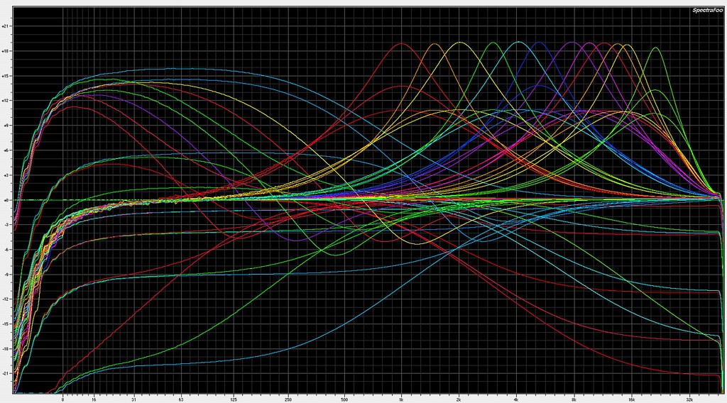
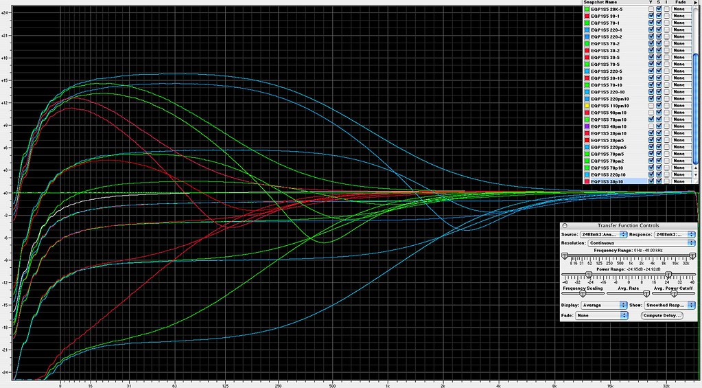
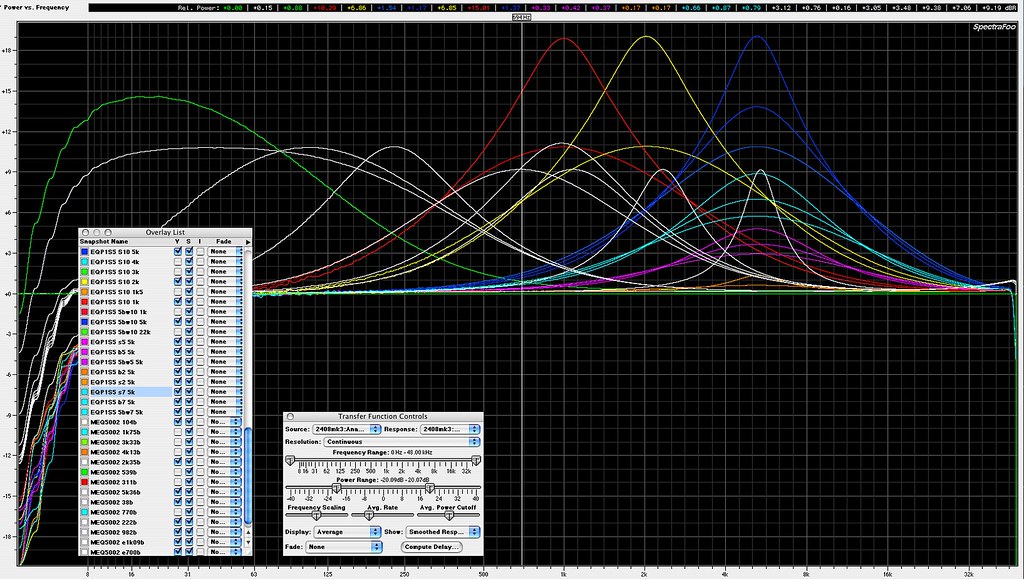
All curves; too much!
full size plot here

12319609614_d4591b7d44_b.jpg


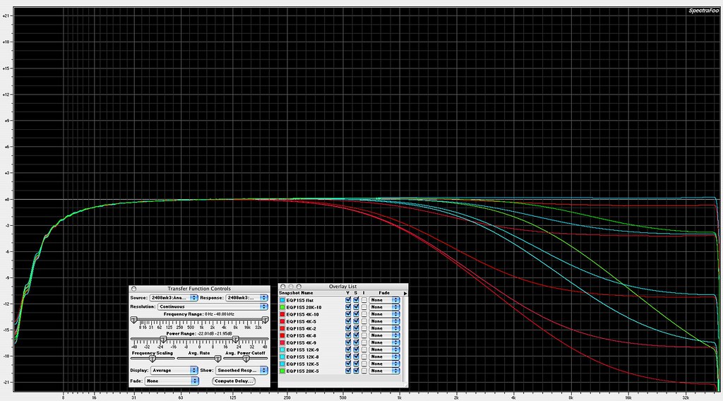
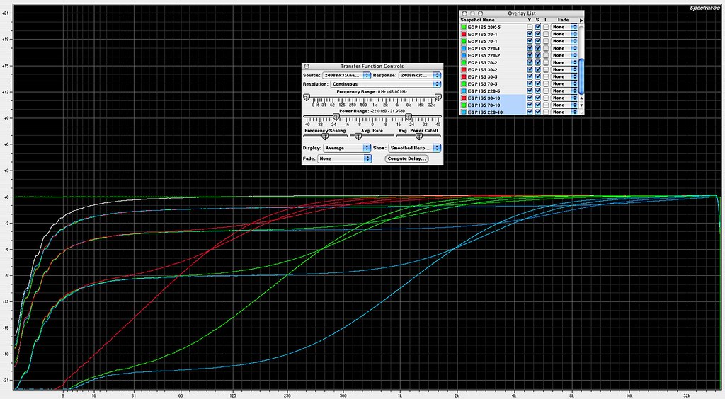
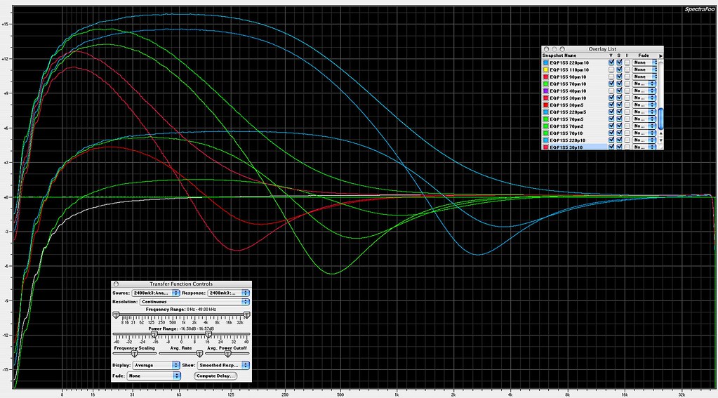
The Lo and Hi attenuation shapes are essentially broad shelves, as in the originals.  The frequency label seems to refer more to the point at which the shelf is flat again, rather than any -3 point as we tend to think today.  This is typical of many 1960ish vintage American EQ's. 

Hi atten curves:
full size plot here

12319324823_5a33aa5c21_b.jpg


Lo atten curves:
full size plot here

12319606544_30ec3aa48a_b.jpg


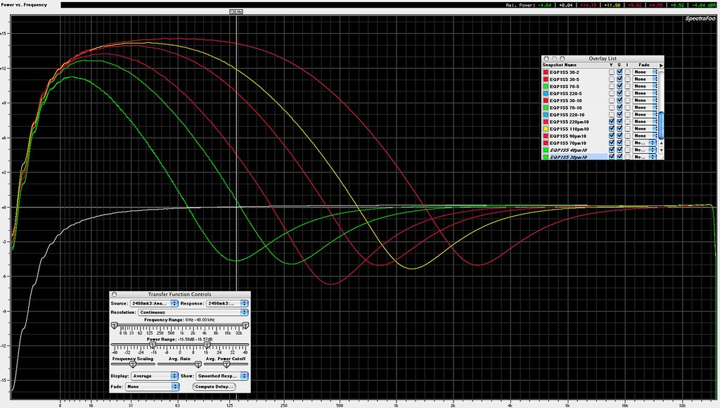
Max boost and atten notch frequencies come out as:
30: 136Hz
40: 272Hz
70: 449Hz
90: 825Hz
110: 1210Hz
220: 2700Hz

A quick glance at the manual for the Manley extended Pultec shows similar results, both here and for all other relevant curves. 
full size plot here

12319606974_09661eb158_b.jpg


Boost and atten on lows, 30/70/220, equal amounts of boost and atten plus full boost, decode from list as '30pm5' means 30Hz plus minus knob setting 5, etc:
full size plot here

12319326483_3fca99ed27_b.jpg


All Lo shapes:
full size plot here

12319326923_5284a19056_b.jpg


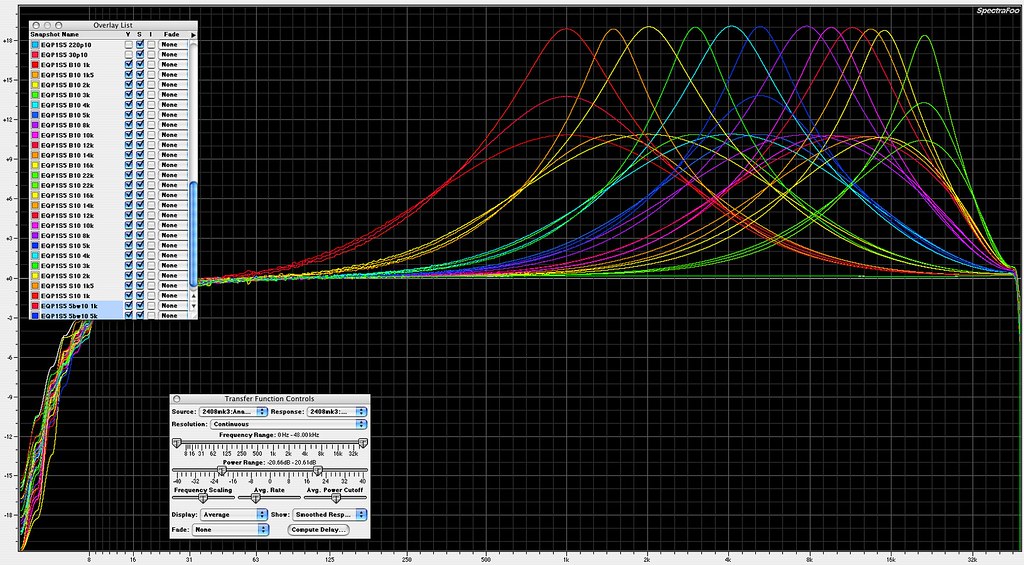
All Hi boosts.  Every frequency shown at max boost for both 'S' and 'B' bandwidth settings, 1K/5K/22K also shown with BW set at center:
full size plot here

12319170175_33e29bec0a_b.jpg


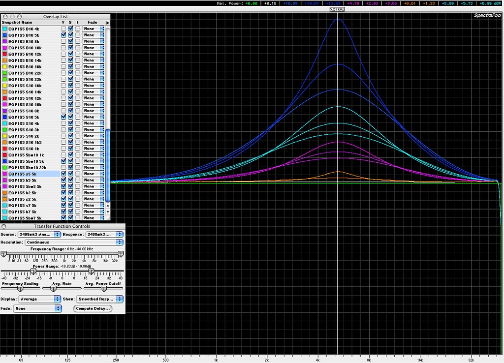
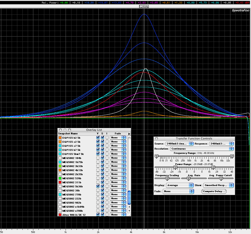
5K boost variations.  Boost knob amounts of 2/5/7/10, with 'S/middle/B' bandwidth settings.  No middle setting for boost of 2 shown:
full size plot here

12319328853_9f45439e9a_b.jpg


5K comparison against an ioaudio MEQ500 mid pultec unit, and a vintage Altec 9061A, the MEQ500 and 9061A both at full boost.  MEQ500 in white, note the much narrower mid pultec shape, and the 9061A in red, having similar shape for equivalent boost range.
12319345135_b926ceb336_b.jpg


A more detailed look at the mid versus the program pultec.  MEQ500 shapes all in white, all at full boost.  MEQ500 40 and 100 low boosts are mods outside of the normal range of operation, and the broader/lower 700 and 1K are also extra mod extensions not normally found. 
full size plot here

12319329763_75ef584cf5_b.jpg


Lots of other MEQ500 measurements starting here:

http://groupdiy.com/index.php?topic=27964.msg494342#msg494342
 
so even a newby? How would Piers (apping) either 992 or if I can get hold of it his Germanium DOA?  So would these sound as good as the JLM?
 
dogma said:
so even a newby? How would Piers (apping) either 992 or if I can get hold of it his Germanium DOA?  So would these sound as good as the JLM?
What's "good" or "bad".......a matter of taste I'd say.
Personally I like the 2520 type DOAs best in this eq,it does some magic and from what I know it was used in the original solid state eq anyway ( meaning the original API 2520).
I'm not sure how far your diy experience goes,but to build the doa is more "fiddly" than building the eq itself.Refer to the build manual on the first page to get an idea.
About the other mentioned DOAs:I have no comparisons made with germanium style or JLMs so far,but did it with the 992.Very open and dynamic,very dimensional sounding,but a bit away from the "true" sound of the 2520s.Remember this eq is definetely a "musician".....
As said my personal taste of course.
The 992s are unbelievable in "surgical" eqs like the sontecs I have.
If you are unsure about building the DOA you can get assembeled ones over at Jeff's Classic API for example,he has the most "important" 2520 types as well as some easier ic-based ones for checking.

Hope to have helped,

Udo.
 
Thank you - I wouldnt attempt to build a DOA - at all! No i mean the actual assembly difficulty. And I mentioned the JLM PEQ as its so well regarded but i realize its subjective. Im wondering if it would be sonically as good as the various high end commercial ones (like the JLM). Thanks for your direction. Im almost certain to do one but your input is really valuable to me!
 
dogma said:
Thank you - I wouldnt attempt to build a DOA - at all! No i mean the actual assembly difficulty. And I mentioned the JLM PEQ as its so well regarded but i realize its subjective. Im wondering if it would be sonically as good as the various high end commercial ones (like the JLM). Thanks for your direction. Im almost certain to do one but your input is really valuable to me!
You're welcome,thanks for the kind words.
Seriously,these are some of the best sounding eqs I have ever had,I own many including non-diy originals.
When I built mine I really had problems to get my hands off of them while listening to various single as well as complex musical signals.Awesome!

Best,

Udo. ;)
 
Udo, that's pretty much how I like my EQP's, with 2520's...

hmm... Maybe we should start selling our 2520s with kits?

dogma said:
So are these easy to assemble? [/qu... couple of melcor 1731 amps to try as well. 
 
jandoste said:
Any good news? :)
I wait it!
Thanks

kante1603 said:
mitsos said:
Any news on this bad boy?

Cheers,

Udo.

FINALLY had some time and got this guy working.  The frequencies are almost all 100% spot on... Still, it needs a new PCB layout. The 3 inductors take up most of the space. My initial plan was to put the inductors underneath, but they didn't fit.. I'd like to keep all the polypro caps because I like the sound, as it is there are a few caps under the PCB, if people don't have a problem with that we can keep the huge caps. 

kante1603 said:
+1,would be a nice christmas present (for me),no? ;D

Best,

Udo. ;)
sorry, Santa ran late.. :) Good thing Christmas happens every year?

Of course, we still need to gauge interest to see if we keep this going or not, but I thought you two would like to know that it works!

cheers!
 

Latest posts

Back
Top