You are using an out of date browser. It may not display this or other websites correctly.
You should upgrade or use an alternative browser.
You should upgrade or use an alternative browser.
etheory - a bunch of projects in progress
- Thread starter etheory
- Start date


Help Support GroupDIY Audio Forum:
This site may earn a commission from merchant affiliate
links, including eBay, Amazon, and others.
etheory
Well-known member
OK, first test successful.
The v2 pcb shows no signs of oscillation whatsoever at any setting.
I've just finished testing the audio path, next step is to engage the compressor and see if that works, then solder up the balancing output stage and see how that goes also.
Just for completeness here is an image I put together of my iterations of trying to replace the operation of the transformer in the front end of the original circuit.
You can all point and laugh at my silliness, but I am sharing in the pursuit of sharing my learning experience.
Iterations
1.) The original circuit - the transformer is not available any more, and I thought it too expensive to try and get a replacement for a beginner and also too heavy to make a small light unit. To also learn more about a simple circuit, I set out to try and electrically replace the input transformer.
2.) My first naive attempt at replacing the transformer in the circuit, produced situations that would break the front end out into oscillation.
Closer analysis of the feedback loop indicated that for certain impulses and frequencies, the loop could produce positive feedback that was self-sustaining.
My feeling is that the phase shift along the path from the emitter of Ts2, through the 1K resistor, and back through to the input of Ts1 in this configuration, was sometimes enough to swing to positive feedback.
3.) The corrected circuit, which closes the loop with negative feedback, and does a much better job of simulating the impedance of the original input transformer. Basically just a simple resistor.
Attachments

etheory
Well-known member
And.... the compressor.... is.... compressing!!!! YAY! (wipes brow).
Everything seems good now - the revision 2 prototype is working perfectly.
Last step is to try out the new balanced output section....
Everything seems good now - the revision 2 prototype is working perfectly.
Last step is to try out the new balanced output section....
etheory
Well-known member
A minor set back.
I soldered up the output stage, and some weird stuff is happening.
However, due to the quasi-dodginess of the wires hanging off of this proto board, I'm sure I've made a simple mistake.
After work tonight I'll get to the bottom of this once and for all!
On the plus side, the final unit looks really really nice.
Kingston
Well-known member
Looking good. Just a thought, but the (unity or low gain) buffer stage for the input might be unnecessary. Unless perhaps you meant it as a boost for seriously overdriving the input stage. Also why inverting?
Just the one debalancing opamp is plenty for an attenuator pot. You could instead use that "extra" NE5532 half for a servo to take out one of the input stage electrolytics.
Just the one debalancing opamp is plenty for an attenuator pot. You could instead use that "extra" NE5532 half for a servo to take out one of the input stage electrolytics.
etheory
Well-known member
Kingston said:Looking good. Just a thought, but the (unity or low gain) buffer stage for the input might be unnecessary. Unless perhaps you meant it as a boost for seriously overdriving the input stage. Also why inverting?
Just the one debalancing opamp is plenty for an attenuator pot. You could instead use that "extra" NE5532 half for a servo to take out one of the input stage electrolytics.
Hi Kingston!
Thanks for the suggestion, I will try that.
The inverting is just so that the output will be in phase. I guess you are right that in theory it's unneccesary, but the original circuit inverts the output, so this does a good job of correcting it.
From memory, though I'll go back and check, the reason that I put the second buffer there was to load Ts1 as little as possible.
I think that putting the 10K potentiometer there directly driving that transistor made it unhappy, hence the extra opamp to drive it more happily.
However I've done a heck of a lot of testing since I made that choice, so your point is a good one that makes me think I should go back and check that.
Whilst it looks like a nice and dense board, I do also feel it's looking like there are a few too many parts now also, so it's a good time to go back and simplify as much as possible....
cheers.


![Soldering Iron Kit, 120W LED Digital Advanced Solder Iron Soldering Gun kit, 110V Welding Tools, Smart Temperature Control [356℉-932℉], Extra 5pcs Tips, Auto Sleep, Temp Calibration, Orange](https://m.media-amazon.com/images/I/51sFKu9SdeL._SL500_.jpg)


$15.98
$16.98
Gikfun Upgraded USB Mini Amplifier Electronic Transparent Stereo Speaker Box Sound Amplifier DIY Kit for Arduino EK1918
Gikfun_Official_Store
Kingston
Well-known member
etheory said:the original circuit inverts the output, so this does a good job of correcting it.
You can invert the debalancing stage input polarity just like a transformer.
But also I'm not sure if TS1 might be sensitive to the output impedance of the stage driving it. Would think it's quite a high impedance input, and thus no effect whatsoever.
etheory
Well-known member
Awesome, I'll simulate that when I get home.
As for the input, yeah, I remember thinking that at one stage, and discounting swapping over the input connections for no apparent reason (maybe just because I hadn't seen it before and hence assumed I was doing something wrong).
Would be a good time to go back and validate that again. Great suggestion. The input servo is a really good idea. There are a "lot" of caps in there, but it had sounded good so I hadn't worried about it before.
etheory
Well-known member
Kingston said:But also I'm not sure if TS1 might be sensitive to the output impedance of the stage driving it. Would think it's quite a high impedance input, and thus no effect whatsoever.
Awesome and bugger at the same time.
You are completely correct and have just saved me another opamp stage from the design (= less parts = less noise), but now I have more board layout work to do (DOH!).
Interestingly, I was sure I had tested this exact suggestion, as it had occurred to me before at one of the early stages of development, but I think there were other issues in the design at that point that got in the way.
Excellent, thanks again.
etheory
Well-known member
Since this thread is called "a bunch of projects", it's time I added another to the bunch.
Here's my 2520 layout of the NTP M100 DOA (not the "B" version, the simpler one).
I'm going to be using this prototype one for a JFet compressor design I've created that looks really really good on the simulator, so now it's time to see how crap it is in real-life ;D:
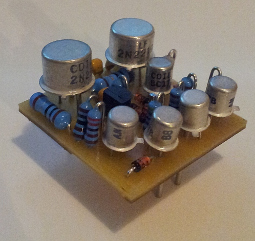
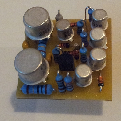
Here's my 2520 layout of the NTP M100 DOA (not the "B" version, the simpler one).
I'm going to be using this prototype one for a JFet compressor design I've created that looks really really good on the simulator, so now it's time to see how crap it is in real-life ;D:
Kingston
Well-known member
etheory said:Awesome and bugger at the same time.
You are completely correct and have just saved me another opamp stage from the design (= less parts = less noise), but now I have more board layout work to do (DOH!).
Interestingly, I was sure I had tested this exact suggestion, as it had occurred to me before at one of the early stages of development, but I think there were other issues in the design at that point that got in the way.
It's a very handy tool with the attenuator. I've used it in at least three projects already. Since you're still doing a board layout, this part works very well with just about any DOA even if their driving capability goes to waste. "more sound" etc. not entirely technical reasons.
What's the output stage like, by the way? Directly from TS6 or something more?
etheory
Well-known member
OK, so, I just snipped the underside of my e274 v2 prototype to implement Kingston's very good suggestion of removing the second opamp at the input stage, and, as the simulation predicted, it's fine.
So I'll be leaving that out.
For completeness sake, I wired it all up again for some testing and recorded some more audio.
You can absolutely total anything with this, it's pretty intense.
You can hear from the clips that if you want clean it's best to go elsewhere. In fact, it's probably not even fair to call this a compressor in the strictest sense - it's really more of a distortion box, but a very interesting one. I've spent as much time as I can making it clean, but this design has it's limitations, and I think I've pushed the main circuit as far as I have the knowledge to do.
I've also managed to decrease the attack time every further now at it's fastest setting, so it's even squishier than before (the Si diodes just don't seem to get themselves into an oscillating mess no matter how hard you try, whereas the Schottky and Ge do).
There was no HPF on the side-chain in this take, so that's why it gets a little murky, I'll record something with a large range of switch settings soonish, once I sort what I'm going to do for my output stage.
As before, this edition is using randomly chosen (i.e. "unmatched") 1N4148's for the compression "bridge".
Enjoy the carnage (same audio as before, but this time pumped much louder) - also please excuse the background noise. If you saw how close my audio cables are running past the power cables, you'd understand.... and it's also not in a box yet.... Just sitting out on my workbench....
http://www.evolutionarytheory.com/wp-content/uploads/2013/04/e274_Limiter_Recording_1N4148_proto_v2.mp3
etheory
Well-known member
Well, you win some, you lose some.
The NTP M100 DOA is pegging it's output at the -ve supply rail, so time to investigate why, when I get home from work I'll take a look. I fear the CNC PCB was made with crap quality raw PCB and there might be some hairline fractures in the copper. So I'll do a pass over it with the magnifying glass and touch up and suspicious traces with some bare wire soldered directly to the tracks. I think that will fix it, provided of course the schematic and parts I've used are actually OK. If I can't get it to work in that form I'll breadboard it up and investigate. What a shame, but at least, again, I'll learn something!
The NTP M100 DOA is pegging it's output at the -ve supply rail, so time to investigate why, when I get home from work I'll take a look. I fear the CNC PCB was made with crap quality raw PCB and there might be some hairline fractures in the copper. So I'll do a pass over it with the magnifying glass and touch up and suspicious traces with some bare wire soldered directly to the tracks. I think that will fix it, provided of course the schematic and parts I've used are actually OK. If I can't get it to work in that form I'll breadboard it up and investigate. What a shame, but at least, again, I'll learn something!
etheory
Well-known member
OK, back to the e274....
The output stage is now working properly.
Last time I tested it I didn't seat the output opamp properly and I think that's where things went a little screwy.
I took it out and put it back in and BAM, balanced lovely output using a simple two stage opamp output, the first stage is non-inverting with some gain to an output cap and short-circuit protection series resistor, and there is also an inverter that outputs to another copy of the output cap and series resistor. Simple, tried and tested, works.
Something I've noticed with the modified input arrangement and single opamp there, is that the phase of the output waveform seems to change drastically now when I turn the input level trimpot.
I have a feeling that replacing the C3 cap with 2.2uF has create too-high a HPF compared to the original 10uF and this is interacting with the input control.... So I might play with this cap and raise it's value, or, I might have to re-install the second input buffer, since maybe it really is loading the input too much at low values. More soon....
MartyMart
Well-known member
Great work, while you may have created a "distortion squash monster" I do like the sound on some of the mp3
examples !")
Reminded me a little of the SSL "Listen mic" comp !
Do you have a "range" or "amount" control? the mp3 sounded like "off" or just "full on"
Keep going, it's all really good stuff.
Marty.
examples !
Reminded me a little of the SSL "Listen mic" comp !
Do you have a "range" or "amount" control? the mp3 sounded like "off" or just "full on"
Keep going, it's all really good stuff.
Marty.
You can probably control the amount of compression fairly well by adjusting the input gain.
For adjustable ratio see etheory's reply #36 in this very thread (page 2).
While we're at it, quick question to etheory:
C1 seems to be one of the timing caps and is 50uF, not 5uF.
Is it possible that you meant another one when it gets to improving the frequency response under compression?
Thanks for this awesome project by the way!!
For adjustable ratio see etheory's reply #36 in this very thread (page 2).
While we're at it, quick question to etheory:
If you want to improve the high frequency response of the original, swap C1 from 5uF to 22uF and drop the 220pF C6 entirely. This gives a tad more high end when under compression.
C1 seems to be one of the timing caps and is 50uF, not 5uF.
Is it possible that you meant another one when it gets to improving the frequency response under compression?
Thanks for this awesome project by the way!!
etheory
Well-known member
Unfortunately there are two instances of C1.mig27 said:C1 seems to be one of the timing caps and is 50uF, not 5uF.
One is on the vca diode-bridge "daughter-board" and one in the main circuit.
I am referring to the one in the main circuit comprising part of the feedback loop around Ts1, which directly sets one of it's pole positions and hence bandwidth.
It's not quite finished yet (damn it's close), but, thank you ;-) It means a lot to know people are interested in my ramblings!mig27 said:Thanks for this awesome project by the way!!
etheory
Well-known member
Kingston said:What's the output stage like, by the way? Directly from TS6 or something more?
I have changed it from something that didn't work very well to something like this, which I think will do the job nicely enough (though I'm sure I could simplify it with a little more though).
I like the idea that the gain is from basically unity to about 12dB with a load of 600R. With a load of 10K it's almost 1dB to 15dB gain.
With a few resistor changes you can almost have any gain range you want, and by using gain rather than attenuation, I was hoping that at the very least I could keep noise a little bit lower (not that it probably matters that much on a design like this....).
Attachments

etheory
Well-known member
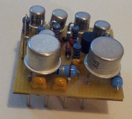
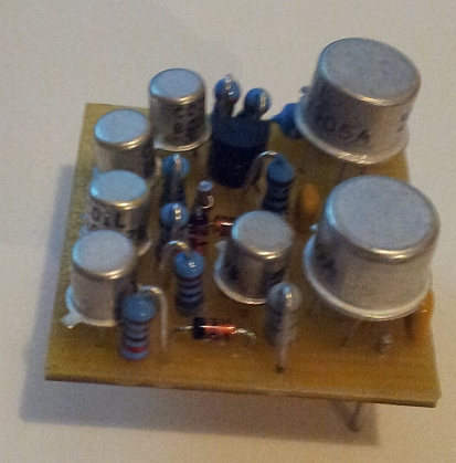
Another quick detour to show another project I've been working on.
The eJFETComp (don't have a proper name for it yet, but basically it'll be yet another JFET compressor).
I've long wanted to try and bring some vaguely-Fairchild-esque vibe to a non-tube comp.
This is the first part of my effort to at least attempt to do that.
The side-chain will be mostly discrete DOA and the audio path should be really really nice.
This prototype is using one of my e2510 DOA's, but a lot of different DOA designs could also fit in that position.
Best part is, the prototype VCA/Audio path is already working perfectly on my breadboard ;-)
Even better is that this particular JFET design can attenuate quite a bit.
The scope waveforms I just saw looked like it should have no issues cleanly doing about 40-50dB (and maybe more) of squashing (if needed), all whilst maintaining some pretty good distortion and noise values (measurements soon....).
Distortion was only just starting to set in at max gain reduction.
Totally different league to the e274 (but intentionally so, I'm pulling out all stops for this one) - as it will be a much more serious beast (more expensive, 3-4 DOAs per channel, and input and output iron) - but more on that later....
Attachments

Similar threads
- Replies
- 4
- Views
- 365
- Replies
- 5
- Views
- 572
- Replies
- 4
- Views
- 409
Latest posts
-

-
-
AKG Perception P220 to Neumann u87 5 min mod ( p200, p100, p400, p420? )
- Latest: Masiusima13
-

-
-

-