


Hello Folks,
great question came in from a customer, thought I'd share the reply here (if that's okay?)
Expat Audio's 3 button controller is designed to use Highly Electric PB613 switches (there are similar ones available from e-switch etc).
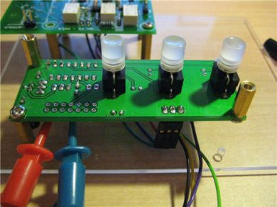
This particular customer couldn't fit it to his case, so he wanted to mount the switches off the case. He wanted to know what parts of the switch he needed to mount, and to which points on the PCB.
The switch circuit works by pulling the microcontroller pin to GND when the button is pushed. (there's some software for debounce etc before smart folks ask!).
So, to connect a PB613, or any other switch, wire 2 wires (the Normally Open, or NO) switches to the circled pins in the attached diagram. The PB613's are DPDT (Dual pole, dual throw). Each switch on the 3 button controlled technically only needs to be SPST, hence the simple minimum requirement to connect 2 pins out of the footprint of 6.
Please let me know if you have any questions.
great question came in from a customer, thought I'd share the reply here (if that's okay?)
Expat Audio's 3 button controller is designed to use Highly Electric PB613 switches (there are similar ones available from e-switch etc).
This particular customer couldn't fit it to his case, so he wanted to mount the switches off the case. He wanted to know what parts of the switch he needed to mount, and to which points on the PCB.
The switch circuit works by pulling the microcontroller pin to GND when the button is pushed. (there's some software for debounce etc before smart folks ask!).
So, to connect a PB613, or any other switch, wire 2 wires (the Normally Open, or NO) switches to the circled pins in the attached diagram. The PB613's are DPDT (Dual pole, dual throw). Each switch on the 3 button controlled technically only needs to be SPST, hence the simple minimum requirement to connect 2 pins out of the footprint of 6.
Please let me know if you have any questions.
